| Last additions |

119 viewsTraxide brain mounted. It's mounted slightly tilted towards the front of the engine bay so as to give as much space as possible to the brake vacuum pipe behind it.29 May 2011
|
|
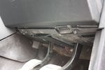
100 viewsRemoving dash undertray29 May 2011
|
|
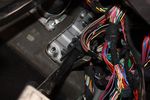
102 viewsLooking for the grommet29 May 2011
|
|
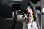
103 viewsGrommet found behind soundproofing29 May 2011
|
|

93 views29 May 2011
|
|
92 views29 May 2011
|
|

109 views29 May 2011
|
|

105 views29 May 2011
|
|

104 views29 May 2011
|
|

102 views29 May 2011
|
|

35 views28 May 2011
|
|
165 views28 May 2011
|
|
172 views28 May 2011
|
|
163 views28 May 2011
|
|
161 views28 May 2011
|
|
155 views28 May 2011
|
|
203 views28 May 2011
|
|
167 views28 May 2011
|
|
149 views28 May 2011
|
|
147 views28 May 2011
|
|
165 views28 May 2011
|
|

44 views28 May 2011
|
|

38 views28 May 2011
|
|
36 views28 May 2011
|
|

40 views28 May 2011
|
|
167 views28 May 2011
|
|
45 views28 May 2011
|
|

35 views28 May 2011
|
|
33 views28 May 2011
|
|

65 views27 May 2011
|
|

40 views27 May 2011
|
|

37 views27 May 2011
|
|
![Filename=LR3_BMW_Ford_ZF_6HP26X-28X_Catalog_with_metal_pans_[1].pdf
Filesize=1194KB
Dimensions=320x240
Date added=26.May 2011 LR3_BMW_Ford_ZF_6HP26X-28X_Catalog_with_metal_pans_[1].pdf](images/thumb_pdf.jpg)
ZF 6HP26X and 6HP28X transmission parts showing various pans2800 viewsThis 42 page pdf is probably the most informative of all the material in this album. It is called a spare parts catalog but is much more than that. The material is specifically for the X variety of ZF six speed transmissions that are in the Land Rover 4WD / AWD models as well as BMW and Ford AWD vehicles.26 May 2011
|
|

32 views26 May 2011
|
|

French speed limits35 views26 May 2011
|
|

180 views25 May 2011
|
|

126 views25 May 2011
|
|
184 views25 May 2011
|
|

74 views25 May 2011
|
|

Time to set up the camp52 views25 May 2011
|
|
62 views25 May 2011
|
|
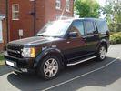
56 views25 May 2011
|
|

Blow Out41 viewsCaravan Tyre Blow out.25 May 2011
|
|
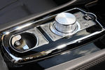
Jaguar auto gear selector63 viewsJaguar auto gear selector25 May 2011
|
|

235 views24 May 2011
|
|

190 views24 May 2011
|
|
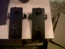
a bar brackets53 views24 May 2011
|
|
49 views24 May 2011
|
|
48 views24 May 2011
|
|

Superinjunction85 viewsBefore Ryan Giggs was exposed as the two faced, nice as pie in public yet screwing any that moves behind closed doors hypocrite he is it was public knowledge that the woman in the story was some slapper from Big Brother but the footballer could not be named. Here we see TNT magazine's top story about her saying the footballer can't be named. Directly underneath is a link to a "related story" was a link to "Ryan Giggs, wife and kids celebrate Manchester United victory"24 May 2011
|
|
41 views24 May 2011
|
|
40 views24 May 2011
|
|
45 views24 May 2011
|
|
51 views24 May 2011
|
|
45 views24 May 2011
|
|
40 views24 May 2011
|
|
Prospeed63 views24 May 2011
|
|
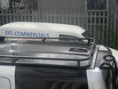
Prospeed52 views24 May 2011
|
|
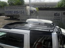
Prospeed45 views24 May 2011
|
|

51 views24 May 2011
|
|

44 views24 May 2011
|
|

48 views24 May 2011
|
|

50 views24 May 2011
|
|

46 views24 May 2011
|
|

47 views24 May 2011
|
|
38 views24 May 2011
|
|
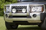
Australian LR D4 Bumper/bar close up62 views23 May 2011
|
|
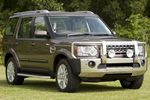
Australian LR D4 Bumper/bar63 views23 May 2011
|
|

79 views23 May 2011
|
|
new Avatar138 views23 May 2011
|
|
Finished D3/D4 Grille Mod142 views23 May 2011
|
|

New Look Disco 3159 views23 May 2011
|
|
prospeed62 views23 May 2011
|
|
prospeed47 views23 May 2011
|
|
prospeed55 views23 May 2011
|
|
prospeed48 views23 May 2011
|
|
![Filename=30813_392881031926_649111926_4681053_735378_n[1].jpg
Filesize=61KB
Dimensions=600x399
Date added=23.May 2011 30813_392881031926_649111926_4681053_735378_n[1].jpg](albums/userpics/18608/thumb_30813_392881031926_649111926_4681053_735378_n%5B1%5D.jpg)
santa pod 2010383 viewsdiscoburt racing a 700hp american truck (i lost)23 May 2011
|
|

Bugarach France221 views22 May 2011
|
|
61 views22 May 2011
|
|
68 views22 May 2011
|
|
53 views22 May 2011
|
|
40 views22 May 2011
|
|

Mid D3/D4 Grille Mod124 views22 May 2011
|
|

43 views22 May 2011
|
|

34 views22 May 2011
|
|
Land Rover Oval49 views22 May 2011
|
|
Colours not Correct60 views22 May 2011
|
|

65 views22 May 2011
|
|

56 views22 May 2011
|
|

52 views22 May 2011
|
|

184 viewsDiscovery D4 Compact22 May 2011
|
|
31 views22 May 2011
|
|
36 views21 May 2011
|
|
35 views21 May 2011
|
|
30 views21 May 2011
|
|

30 views21 May 2011
|
|
29 views21 May 2011
|
|
29 views21 May 2011
|
|
28 views21 May 2011
|
|
27 views21 May 2011
|
|
21 views21 May 2011
|
|
20 views21 May 2011
|
|
18 views21 May 2011
|
|
19 views21 May 2011
|
|
19 views21 May 2011
|
|
19 views21 May 2011
|
|
18 views21 May 2011
|
|
19 views21 May 2011
|
|
19 views21 May 2011
|
|
18 views21 May 2011
|
|
18 views21 May 2011
|
|
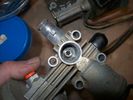
18 views21 May 2011
|
|
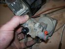
19 views21 May 2011
|
|
18 views21 May 2011
|
|
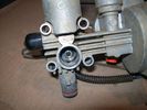
18 views21 May 2011
|
|
21 views21 May 2011
|
|
21 views21 May 2011
|
|
19 views21 May 2011
|
|
18 views21 May 2011
|
|
20 views21 May 2011
|
|
19 views21 May 2011
|
|
20 views21 May 2011
|
|
18 views21 May 2011
|
|
19 views21 May 2011
|
|
16 views21 May 2011
|
|
16 views21 May 2011
|
|
16 views21 May 2011
|
|
16 views21 May 2011
|
|
16 views21 May 2011
|
|
17 views21 May 2011
|
|
16 views21 May 2011
|
|
15 views21 May 2011
|
|
15 views21 May 2011
|
|
16 views21 May 2011
|
|
15 views21 May 2011
|
|
15 views21 May 2011
|
|
13 views21 May 2011
|
|
14 views21 May 2011
|
|
16 views21 May 2011
|
|
16 views21 May 2011
|
|
17 views21 May 2011
|
|
23 views21 May 2011
|
|
36 views21 May 2011
|
|
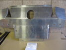
32 views21 May 2011
|
|
30 views21 May 2011
|
|
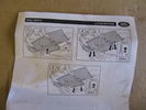
34 views21 May 2011
|
|
75 views21 May 2011
|
|
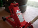
81 views21 May 2011
|
|
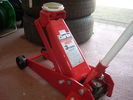
62 views21 May 2011
|
|
72 views21 May 2011
|
|
62 views21 May 2011
|
|
67 views21 May 2011
|
|
67 views21 May 2011
|
|
61 views21 May 2011
|
|

24 views21 May 2011
|
|
MAS 1196 views55K miles pre-cleaning20 May 2011
|
|
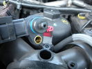
MAS 179 views55K miles after cleaning20 May 2011
|
|

General AT169 views19" General AT with Pirelli Scorpion20 May 2011
|
|
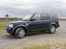
D4 HSE Baltic Blue292 views20 May 2011
|
|
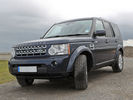
D4 HSE Baltic Blue244 views20 May 2011
|
|
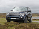
D4 HSE Baltic Blue220 views20 May 2011
|
|

D4 HSE Baltic Blue288 views20 May 2011
|
|

D4 HSE Baltic Blue244 views20 May 2011
|
|
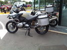
The GS Adventure59 views20 May 2011
|
|

The GS Adventure41 views20 May 2011
|
|

ScanGauge II Manual 340 viewsThese are the setup instructions etc for the ScanGauge II version 5.1 There are newer versions that can be downloaded from the website www.scangauge.com as the software is subject to update; also the ScanGauge unit you purchase can later be sent in for updates as you might wish.20 May 2011
|
|

79 views19 May 2011
|
|

346 views18 May 2011
|
|

249 views18 May 2011
|
|

Prospeed wheel carrier234 viewsProspeed spare wheel carrier18 May 2011
|
|

210 views18 May 2011
|
|

XRS cross bar228 viewsXRS cross bar with jerry can holder18 May 2011
|
|

108 views18 May 2011
|
|
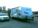
70 views18 May 2011
|
|

41 views18 May 2011
|
|

35 views18 May 2011
|
|

Voltmeter78 views18 May 2011
|
|
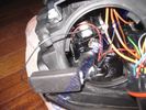
LED resistor fix67 views17 May 2011
|
|

66 views17 May 2011
|
|

LED indicator 92 Ultrabright LED71 views17 May 2011
|
|
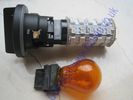
LED indicator vs standard capless 315660 views17 May 2011
|
|
LED sidelight63 views17 May 2011
|
|

76 views17 May 2011
|
|

led65 views17 May 2011
|
|

led64 views17 May 2011
|
|

led module55 views17 May 2011
|
|

led68 views17 May 2011
|
|

Air Suspension Wiring Sheets3026 viewsThese two sheets show the wiring and fuses related to the operation of the air suspension system. Fuses F3E, F26E, and F35P are shown as well as the interior up down switch and the wheel height sensors.
As with all pdf's, you can rotate them to view plus download and or print out as you wish.17 May 2011
|
|

skimmer532 views17 May 2011
|
|

skimmer432 views17 May 2011
|
|

skimmer325 views17 May 2011
|
|

skimmer229 views17 May 2011
|
|

skimmer 122 views17 May 2011
|
|

Bulgarian Seaside42 views17 May 2011
|
|

Bulgarian Mountains37 views17 May 2011
|
|

Off Road in Bulgaria39 views17 May 2011
|
|
37 views16 May 2011
|
|
51 views16 May 2011
|
|

36 views16 May 2011
|
|
44 views16 May 2011
|
|
49 views16 May 2011
|
|
53 views16 May 2011
|
|
51 views16 May 2011
|
|
50 views16 May 2011
|
|
51 views16 May 2011
|
|
49 views16 May 2011
|
|

ZF 6HP26 Metal Pans, (top and bottom views), and separate Filter top and bottom views.1755 viewsThis single sheet pdf two views of the ZF metal pan for the 6HP26 transmission. The inside view shows the two magnets; the other is the bottom view. Also visible are the transmission bottom oil fill and oil drain holes that are sometimes utilized where access to the side fill is not possible. The ZF part number for the metal pan kit for our 6HP26X six speed is 1068_103_820_01 This includes the 21 shorter Torx screws, the metal pan gasket, and the separate oil filter as well as round filter seal. The ZF six speed LifeGuard6 transmission oil is extra. 16 May 2011
|
|
75 views15 May 2011
|
|

My overland prepped Discovery65 views15 May 2011
|
|
45 views15 May 2011
|
|

42 views15 May 2011
|
|
43 views15 May 2011
|
|
90 views15 May 2011
|
|
76 views15 May 2011
|
|
72 views15 May 2011
|
|
69 views15 May 2011
|
|
56 views15 May 2011
|
|
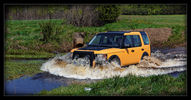
Swimming :)53 views15 May 2011
|
|

47 views15 May 2011
|
|

46 views15 May 2011
|
|

39 views15 May 2011
|
|

Front in Yellow and Black65 views15 May 2011
|
|

Back in Saffron Yellow Mat and Black Mat52 views15 May 2011
|
|

Side in Saffron Yellow Mat59 views15 May 2011
|
|

Front with Winch, A-Bar, Front LIght Guards and Driving Lamps57 views15 May 2011
|
|

Rear Lamp Guard45 views15 May 2011
|
|

Brand new toy :)39 views15 May 2011
|
|

58 views15 May 2011
|
|

Ugly green is amost gone!52 views15 May 2011
|
|

ORACAL 970 - Sarffron Yellow Mat51 views15 May 2011
|
|

54 views15 May 2011
|
|

Those holes needs to be bigger43 views15 May 2011
|
|

Bumper cut46 views15 May 2011
|
|

Front view48 views15 May 2011
|
|

Side view45 views15 May 2011
|
|

Ta da! READY!54 views15 May 2011
|
|

The green one need to be cut39 views15 May 2011
|
|

Connected to the Rear Seat Heat fuse39 views15 May 2011
|
|

42 views15 May 2011
|
|

41 views15 May 2011
|
|

45 views15 May 2011
|
|

Before lifting45 views15 May 2011
|
|

New toys - 2" lift Lovells Gas Legend - (+100kg springs)50 views15 May 2011
|
|

47 views15 May 2011
|
|

46 views15 May 2011
|
|

48 views15 May 2011
|
|
32 views15 May 2011
|
|
32 views15 May 2011
|
|
33 views15 May 2011
|
|
36 views15 May 2011
|
|
31 views15 May 2011
|
|

36 views15 May 2011
|
|

Floor Console Upper Panel62 views14 May 2011
|
|
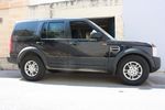
67 views14 May 2011
|
|

50 views14 May 2011
|
|
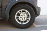
55 views14 May 2011
|
|

45 views14 May 2011
|
|

Frame Jacking Points showing where holes are located.1078 viewsThe four points marked with the arrows show where the holes in the underside of the frame are located such than one could insert a trolley jack pin type lifting adapter, (or as designed), the official LR scissors jack.14 May 2011
|
|
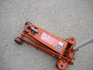
Trolley Jack Adapter817 viewsThis shows my 2.5 long ton, (2,540 kg, 5,600 pounds), trolley jack with the pin adapter that slots up into the round holes on the underside of the frame.
Use of the adapter when lifting by the left rear wheel ensures that I will not be jacking on the air compressor support; on the other three corners, it is much safer than merely jacking directly on the nearly flat narrow underside of the frame rail.14 May 2011
|
|

103 views14 May 2011
|
|
![Filename=P110511_08_42_[01].jpg
Filesize=283KB
Dimensions=1280x960
Date added=14.May 2011 P110511_08_42_[01].jpg](albums/userpics/13713/thumb_P110511_08_42_%5B01%5D.jpg)
7 Ton Log Splitter25 views14 May 2011
|
|
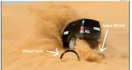
D4 crash52 views14 May 2011
|
|

33 views14 May 2011
|
|

29 views14 May 2011
|
|

G4 90deg30 views14 May 2011
|
|

Tailgate Actuator DIY.98 viewsIf your stuck with the problem of the boot not opening and can't wait for the replacement, here's the DIY.14 May 2011
|
|

ZF6HP26X fluid fill checking procedure2242 viewsThis are the single page ZF instructions for checking the fluid level in the 6HP26X six speed automatic that is in the LR3.
Included sketches show where the fill and drain plugs are located and that it requires a 8mm hex wrench for the filler plug and a 10mm for the drain for the plastic pan.14 May 2011
|
|
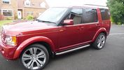
50 viewsSide Bars on Red D313 May 2011
|
|
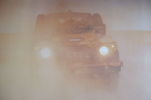
Defender in the Fog, another day on the job.456 viewsThis is another normal work day for a Defender - actually the jpg is from a Land Rover advertising shot, but it may just not be a set up one. I think it is an actual working Defender. Note the visible front tow hook and how the hi lift is just rope tied on; also the normal stock headlights and I guess dual spare tyres - just another day on the job.13 May 2011
|
|

18 views13 May 2011
|
|
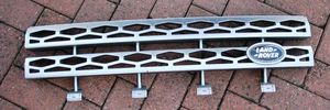
66 views13 May 2011
|
|

Power Door Lock wiring diagrams524 viewsI thought I would include this 5 page power door lock wiring diagram pdf here as well.
When the pdf loads, if the views are vertical, it may be that you can right click on your mouse and a box will come up that will allow you to rotate the views clockwise so that the sheets are horizontal. Alternatively you can download the file and print each sheet yourself.12 May 2011
|
|

56 views12 May 2011
|
|

77 views12 May 2011
|
|
UA057747 views12 May 2011
|
|

Key in Ignition Electrical Wiring Diagram1043 viewsThis shows the key in ignition wiring, (LGW, 1.5D), running from the key lock cylinder to the Central Junction Box, (CJB), thru 5 amp fuse F40P, located in the fuse box behind the lower glove box door.
You can remove the 5 amp fuse and the good news is that the ignition chime will not sound any longer; the bad news is that a bunch of other circuits that rely on knowing if the key is in or out no longer work.
Also note the Transponder Coil D219 reference.12 May 2011
|
|
Sea breeze front24 views12 May 2011
|
|
Sea breeze front22 views12 May 2011
|
|
Sea breeze front22 views12 May 2011
|
|

trailer_and_off_road_height135 views12 May 2011
|
|
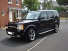
61 views12 May 2011
|
|
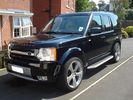
63 views12 May 2011
|
|

45 views12 May 2011
|
|

43 views12 May 2011
|
|
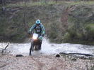
38 views12 May 2011
|
|

46 views12 May 2011
|
|

49 views12 May 2011
|
|

45 views12 May 2011
|
|

47 views12 May 2011
|
|

41 views12 May 2011
|
|

31 views12 May 2011
|
|

29 views12 May 2011
|
|

38 views12 May 2011
|
|

32 views12 May 2011
|
|

25 views12 May 2011
|
|

25 views12 May 2011
|
|

22 views12 May 2011
|
|

23 views12 May 2011
|
|

24 views12 May 2011
|
|

25 views12 May 2011
|
|

23 views12 May 2011
|
|

50 views12 May 2011
|
|

48 views12 May 2011
|
|
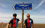
TPT start29 views11 May 2011
|
|
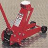
63 views11 May 2011
|
|

40 views11 May 2011
|
|

pic of lock and key49 views11 May 2011
|
|

38 views11 May 2011
|
|

Llamsrecovery mode installation53 viewsSpring lock inconspicuous11 May 2011
|
|

Add A Circuit Littelfuse Data sheet2267 viewsThe switch connects to what Littelfuse brand calls an Add-A-Circuit model FMH200BP which is an adapter that plugs in place of a Mini fuse and then has space for two Mini fuses, (original and a second one). In this install, only the original 5 amp fuse was used - adapter was so as to route power from fuse box thru fuse, then rocker switch, and then back to fuse box.
Before you install the Add A Circuit for this application, take an ohm meter and trace out the circuit path of the four slots that fuses could insert into. The path is more complicated than one might first think. As such, the orientation of the fuse holder in the socket matters for this application - that is for a circuit diverter, rather than accessory adder.
11 May 2011
|
|

43 views10 May 2011
|
|
85 views10 May 2011
|
|
72 views10 May 2011
|
|
77 views10 May 2011
|
|
68 views10 May 2011
|
|
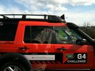
241 views10 May 2011
|
|
215 views10 May 2011
|
|

97 views10 May 2011
|
|

81 views10 May 2011
|
|

81 views10 May 2011
|
|

cool dog80 views10 May 2011
|
|
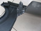
95 viewsbottom lug inside upside down round & round we go view10 May 2011
|
|

116 viewsbottom lug. try to cut around & leave intact10 May 2011
|
|

101 views10 May 2011
|
|

89 views10 May 2011
|
|

149 views10 May 2011
|
|

97 viewsupright cut outs10 May 2011
|
|
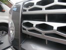
135 views10 May 2011
|
|
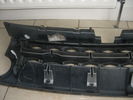
111 viewsnew inner fitted to existing outter10 May 2011
|
|

115 views10 May 2011
|
|

100 views10 May 2011
|
|
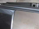
104 viewsexisting grille cut out along rib/line10 May 2011
|
|

90 views10 May 2011
|
|
58 views10 May 2011
|
|

Exploded Parts view calling up 6R60/80 and 6HP26/28 variations3098 viewsThis single page jpg exploded parts view indicates some commonality between the Ford and ZF versions of the early and later six speed units. Technically this sheet is for the RWD units as there are variations between plain RWD units, 4WD, and AWD. The transmission in the LR3 is called by ZF to be a 6HP26X and by LR in some publications, the 6HP2610 May 2011
|
|
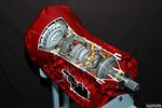
Ford 6R60 six speed cutaway showing torque converter.2188 viewsThis is a cutaway of the Ford 6R60 six speed which is a Ford license built version similar to our ZF 6HP26 six speed speced on early 3's.
The newer 3's and 4's have the ZF 6HP28. The Ford version is called the 6R80 and variations of it are used on the Raptor. As such, the Raptor metal pan can be installed on the 3's tranny but the deeper Ford Raptor pan does not have a drain plug. 10 May 2011
|
|

41 views10 May 2011
|
|
28 views10 May 2011
|
|
23 views10 May 2011
|
|

77 views09 May 2011
|
|
141 views09 May 2011
|
|

67 views09 May 2011
|
|
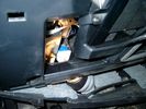
Smooth Talker Amplifier Box mounted below near steering column.179 viewsThe gold look box due to the lighting, (actually black), is the antenna amplifier located near the steering column. It can be put anyway but this seemed an OK location as I ran the antenna connector cable rearward from here to the back corner of the 3 and then up to the underside of the roof glass at the rear. The blue/white thing is the brake light switch that often must be replaced. See the Brake Light Switch file within this Gallery regarding the switch replacement.09 May 2011
|
|
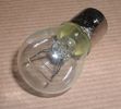
Land Rover Stop Tail Light dual filament bulb nominal 12 volt 21 / 5 watt filaments1412 viewsThis is the Land Rover part number 264590 dual filament bulb, (P21/5), that inserts into the upper two tail lamp receptacles. In the upper one, both filaments function, in the lower one, only the 5 watt tail light filament functions.
I regard it as not a good practice to routinely switch bulbs when the tail light filament, (5 watt), burns out on the lower bulb. The broken filament can jiggle over onto the brake light filament, (21 watt), and short the circuit to ground or something else not predicable.
There are also arguments to say that quality control is better on the Land Rover marketed bulbs than say far east sourced bulbs. Filament construction, and hence resistance can vary and mislead the current sensing circuits monitoring the signal light systems. Also when the bulbs are properly installed, all filaments should be standing vertically and not at any slope.
These are the sort of obscure circumstances that can lead to false trouble messages on the display, dropping to the stops, and subsequent concerns - all over a tail/signal light bulb.
For example, the filament life of both the tail light and the brake light filaments in the P21/5 bulb is significantly less than the USA common 1157 dual filament bulb, (1000/250 vs 5000/1200 hours); brightness in the P21/5 is a bit more, (3cp/35cp vs 3cp/32cp where cp is candle power), but current consumption is oddly less, (0.44a/1.86a vs 0.59a/2.10a where a is amps). It is the quest for efficiency vs maintenance trade off.09 May 2011
|
|

D3 infotainment37 views09 May 2011
|
|

D4 infotainment34 views09 May 2011
|
|
gsxr60068 views09 May 2011
|
|
halo club99 views09 May 2011
|
|
halo club88 viewshalo club09 May 2011
|
|

85 views09 May 2011
|
|

85 views09 May 2011
|
|

65 views09 May 2011
|
|

91 views09 May 2011
|
|

Before spacers66 views09 May 2011
|
|
Increased standard height via MSV264 views09 May 2011
|
|
37 views09 May 2011
|
|
40 views09 May 2011
|
|

41 views09 May 2011
|
|
34 views09 May 2011
|
|
35 views09 May 2011
|
|
34 views09 May 2011
|
|
33 views09 May 2011
|
|
37 views09 May 2011
|
|
35 views09 May 2011
|
|
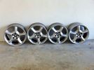
BMW X5 17" wheels51 views09 May 2011
|
|
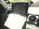
Netbook mount with Fugawi55 views09 May 2011
|
|

Standard Height49 views09 May 2011
|
|

Brake Light Switch, Find, Remove, and Install Instructions 7786 viewsThis is a two page doc outlining where to find the brake light switch, how to remove it, and then install the new one.
Note, do not move the brake pedal when removing or installing the switch. Let the brake pedal hang where it wants to. The switch design is actually cunning, and as such is supposed to make the removal and install fool proof. Hence if you think too much about it, you can wreck the new switch.
If you want to inspect the interior of the switch, wait until you have removed the old switch. You can then just unsnap the blue from the white to get it apart. Inside, the switch is quite simple, (no circuit boards), but it will probably show black dust from failing contacts.
I think the reason the switch fails is that the Normally Open, (NO), contacts of the brake light contacts were made too light to carry the current load for make and break of the tail light filaments. I also think the black dust created then fouls the Normally Closed, (NC), second set of contacts for the ABS circuit. As such, the Normally Closed contacts become intermittent in operation and display as a fluctuating open and closed circuit condition to the ABS system when the ABS should be seeing a steady closed circuit. Hopefully the replacement switch contacts are more robust and may be as I recently replaced my switch again just as a matter of maintenance. While in a redesign, ideally the NC contacts should be sealed or at least separated from the NO contacts, when I inspected the removed switch, this time there was no black dust present.
Probably the removed switch will have a Land Rover oval logo moulded into it, the new one, FOMOCO.09 May 2011
|
|
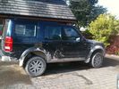
Driffield cack!67 views09 May 2011
|
|
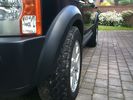
After fitting spacers71 views30mm spacers fitted front & rear.09 May 2011
|
|
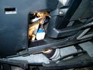
Brake Switch Visible thru Opening4941 viewsThe blue and white bit is the switch; the sort of gold appearing box,(it is really black), you will not see in your 3 as it is a Smooth Talker brand amplifier for my Blackberry phone antenna. This install is detailed in the SmoothTalker phone antenna section of my gallery.
One way to remove and install the switch is to lower the "horizontal" panel above the brake pedal as shown where the flashlight head is located. To actually remove the switch, you slide your hand thru the gap and rotate the switch clockwise 1/4 turn while watching thru the rectangular opening. Installation of the new switch is the reverse of above - 1/4 turn counterclockwise.
Before you remove the switch, note its orientation - horizontal with electrical wires to the left. That is the way it should look after replacement as well.
The second time I replaced the switch, I did it all thru the rectangular opening and did not remove the horizontal panel - that is experience helping out.
The knee kick you have to remove regardless. It is sort of hinged at the bottom so you just pull at the top and sort of rotate the knee panel and then pull upwards for two plastic "fingers" to clear the slots they reside in.09 May 2011
|
|

Switch is blue colour thing thru the rectangular opening.3151 viewsThe blue coloured plastic bit thru the rectangular opening is the brake light switch. The fist time, I found it easier remove the switch by dropping the horizontal plastic panel, (two screws), and then slipping my hand in and rotating the switch clockwise 1/4 turn. The second time, I was able to remove the switch thru the rectangular opening and did not need to remove the horizontal lower panel. Obviously, I had to remove the sloping knee pad panel, (note sort of hinged at the bottom so pull back from the top.)
Regardless, do not touch the brake pedal - just let it sit where it wants to. One has to first remove the angled knee pad panel that sits under the steering wheel. It can be pulled from the top corner at the door side. Pulling releases a pair of those U shaped metal clips that LR loves so dearly. You have to pull quite hard. The bottom is held by a couple of plastic fingers in a couple of slots so you pull at the top till the two clips release and then rotate the panel and pull upwards a bit.
To remove the switch, you rotate it clockwise and pull outwards. Rotating the switch clockwise automatically retracts the plunger back into the switch body away from the brake pedal arm.
Similarly when you install the new switch, the required 1/4 turn anti clockwise rotation action releases the plunger so it lays up against the brake pedal arm and at the same time, secures the switch in place.
To remove the electrical wires, the switch will drop below the horizontal pad and hang from the wires so unclipping the electrical connector plug is fairly easy to do.09 May 2011
|
|

Black Deposits to interior of Brake Light Switch2834 viewsThere are two contacts, one on each side of the vertical plunger under the copper metal. The set of normally open contacts on the left side that carries the power for the brake light filaments, (15 amp fuse F15P), is apparently not heavy enough as the contacts deteriorate and generate the black residue.
The set of normally closed contacts on the other side appear to be sized OK. There is not as much current, (5 amp fuse F66P), flowing thru the contacts to the ABS module, however the contacts are likely adversely affected by the black residue produced by the other deteriorating set of contacts.
One presumes/hopes that the newer replacement switch now has contacts heavy enough to carry the brake light power. It would be ideal if the ABS set of contacts were sealed from the brake light contacts to prevent contamination of the normally closed set of contacts. 09 May 2011
|
|

Black Deposits on Brake Light Switch Plunger2733 viewsThis jpg I got off another forum and is typical of what one will see when one opens up the removed brake light switch. The black powder is residue from arcing of one of the pair of contacts within.
Hopefully the newer switches with the FOMOCO logo moulded into the plastic are improved from the Land Rover logo marked early units, however I doubt it.
The Ford part number is SW-6572 and/or 7E5Z-13480-A as used on the 2006 to 2009 Ford Fusion's and Mercury Milan's; the Land Rover part number is XKB500110. Cost of switch could be about twenty five dollars. A previous LR part number for the switch was XKB500030, so hopefully the newer LR part number, XKB500110, reflects some improvement in reliability.
It is possible that the new switches are better as I installed a replacement 72,000 km, (45,000 miles) later, at 195,000 km (121,000 miles). When I took the removed switch apart to inspect, it was clean inside. There was no black dust - the switch looked like new, hence they must be improved now.09 May 2011
|
|
62 views09 May 2011
|
|
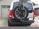
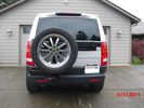
This is how to make it all work. Backup sensor on carrier43 viewsHighlift, ax and shovel. Yes they are matching colors. What else?09 May 2011
|
|
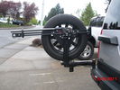
highlift and new sensor wire loom30 viewsNew wire loom added to protect sensor wires and keep things sanitary looking
. Highlift jack mount arms added and gas strut09 May 2011
|
|
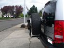
Highlift mount added27 viewsHighlift mounted in this position allows for any length with out overhead clearance issues if stood upright09 May 2011
|
|
Receiver for toy rack38 viewsSensor bar was made of same heavy tube that the carrier was made from allowing a small 1 1/4" receiver to be placed on it for a multitude of toy racks of my choice. Rack adjust in and out of receiver.09 May 2011
|
|
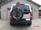
New mods for carrier. Backup sensor moved to the tire carrier. Toy rack and highlift mounts.38 viewsSon wanted all the toys on the carrier. I just wanted easy removal for a good clean look. 09 May 2011
|
|
Sensor bar33 viewsSensor has been moved out to tire carrier where it should be. It does not pick up the tire anymore. "no faults". 09 May 2011
|
|

Land Rover Brake Light switch XKB5001102676 viewsThis is what the switch looks like when removed from the parts box. Note that the plunger is recessed back into the body and when installing, the process of rotating the switch body 1/4 turn anticlockwise releases the plunger so it pops longer and engages the brake pedal. If you look down on the plunger you can see curved slots where the rotation takes place.
Do not try to rotate the new one - play with the one you remove. Also do not press on the brake pedal when removing or installing as you will damage the plunger - this is one of the reasons the plunger is retracted into the body for installation. It is also for this reason that if you try to confirm the operation of the switch contacts with an ohm meter by pressing the plunger, the switch will appear not to function as one might anticipate. Have faith, the switch will however, once installed and the plunger is in full motion.09 May 2011
|
|

Stop Light Lamp Circuit pdf2464 viewsThis pdf shows the brake light circuit for the NAS LR3.
Note that power for the brake light bulbs can come either thru the brake light switch power feed /contacts plus also from the Hill Decent Control, (HDC), system relay located within the Central Junction Box, (CJB) - yes two separate sources of power for the brake light bulbs. This would tend to explain how a brake light circuit concern shows up as a hill decent fault message; also why lesser vehicles without hill decent braking mechanisms, (HDC), never display this sort problem when a brake light bulb or switch acts up. You never have a problem related to a system that does not exist.
Additional evidence of the relationship of the HDC and the tail light circuit is demonstrated by when the HDC actually acts to slow the 3 down, the brake lights automatically illuminate even if the slowing action was merely retarding the engine speed or shifting to a lower gear, (in other words, no foot on the brake pedal).
There is also a tie in to the Cruise Control and hence a failing brake light switch can affect cruise operation or just create false Cruise Control messages. To further complicate the issue, while there are no messages generated, operation of the radiator electro viscous fan can also be negatively affected by the fouled set of secondary contacts within the brake light switch. This is all because the NC contacts within the brake switch send misleading messages to the ECU.
While the ground wire design is similar to other vehicles, note the grounds for the brake light filament and the reverse light filament are common on each side. That means that if one has a non functioning brake light on one side, the reverse light may not also work or that some problem with the reverse lights could back feed into the brake lights. This situation while unusual, can result when grounds are corroded probably due to swimming in rivers and creeks or just routine driving in a marine environment.09 May 2011
|
|

42 views08 May 2011
|
|
A bit of muck!48 views08 May 2011
|
|
Defender stuck in the mud run!42 views08 May 2011
|
|

Course35 views08 May 2011
|
|

Hill climb36 views08 May 2011
|
|
Defender recovered by RRC & tray back.39 views08 May 2011
|
|

Front Runner Y style rear tyre carrier 581 viewsThis is the new Y or D shaped Front Runner, (out of South Africa), brand of rear bumper mount tyre carrier.
The big deal is the new self latching mechanism.07 May 2011
|
|

new ATs19 views07 May 2011
|
|

33 views07 May 2011
|
|

wha's35 views06 May 2011
|
|
44 views06 May 2011
|
|
55 views06 May 2011
|
|

58 views06 May 2011
|
|
71 views06 May 2011
|
|
50 views06 May 2011
|
|
50 views06 May 2011
|
|
50 views06 May 2011
|
|
| 234288 files on 586 page(s) |
 |
 |
 |
 |
 |
 |
 |
490 |  |
 |
 |
 |
 |
|