| Search results - "installation" |
214 viewsReady for installation
|
|

Llamsrecovery mode installation53 viewsSpring lock inconspicuous
|
|

94 viewsOut at the C pillar. From here wires were threaded through the rear seatbelt anchor point into the commercial box, which is the hub of all the wiring and CarPC installation
|
|
D4 2010 installation57 views
|
|

D3 installation64 views
|
|

new screens fitted 26 viewsAfter installation
|
|
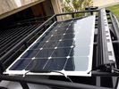
solar roof install437 viewsMore or less wrapped up my solar installation today. I added a Grape Solar Flex 100W panel, it's adequate to keep the vehicle topped off with the Fridge running, and Ham, but it could lose some ground if transmitting depending on how much, 2 would be awesome. One is enough, but barely. I am quite impressed with the Grape Solar flex panel version 2.0.
https://www.facebook.com/DifferentialPartsUS
|
|

501-12-cool-box install instructions / german language63 viewsCool Box Discovery 4 installation instructions - german version
|
|

124 viewsThis is the installation guide from the manufacturer
|
|

Rosen A7 \'alternative\' install459 views
|
|

Thread upload4 viewsImage uploaded in new thread
|
|

Altox WBUS-4 Installation in Discovery 3125 viewsstep by step with pictures how to install the Altox WBUS-4 in the Discovery 3 in footwell
|
|

Altox_Installation_on_D3-RRS_up_to_200936 views
|
|

how to install Altox WBUS-4 in engine room on Discovery 395 viewsthis is to show how to install the Altox WBUS-4 in engine room of a Discovery 3, but i would recommend to install it inside car in footwell, see other PDF in this album
|
|

199 viewsInstallation Instructions for ACM
|
|
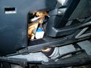
Brake Switch Visible thru Opening4933 viewsThe blue and white bit is the switch; the sort of gold appearing box,(it is really black), you will not see in your 3 as it is a Smooth Talker brand amplifier for my Blackberry phone antenna. This install is detailed in the SmoothTalker phone antenna section of my gallery.
One way to remove and install the switch is to lower the "horizontal" panel above the brake pedal as shown where the flashlight head is located. To actually remove the switch, you slide your hand thru the gap and rotate the switch clockwise 1/4 turn while watching thru the rectangular opening. Installation of the new switch is the reverse of above - 1/4 turn counterclockwise.
Before you remove the switch, note its orientation - horizontal with electrical wires to the left. That is the way it should look after replacement as well.
The second time I replaced the switch, I did it all thru the rectangular opening and did not remove the horizontal panel - that is experience helping out.
The knee kick you have to remove regardless. It is sort of hinged at the bottom so you just pull at the top and sort of rotate the knee panel and then pull upwards for two plastic "fingers" to clear the slots they reside in.
|
|
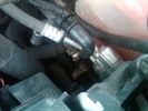
Breather Cap Installed1970 viewsThe black L shaped tube is is the Gore manufactured, (the Gore-Tex people), LR4 Breather Valve installed in an LR3. Naturally the installation looks similar to what one sees on an LR4 or RRS as the Gore breather valve is now OEM for new production.
The part number of this upgraded front differential breather valve is LR019450 and costs about thirty dollars.
|
|
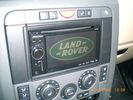
Job done - after adding nice start screen :-)237 viewsPinoeer AVIC-F910BT installation
|
|

39 views
|
|

Installation completed67 views
|
|
179 views
|
|
176 views
|
|
143 views
|
|
135 views
|
|
160 views
|
|
181 views
|
|
176 views
|
|
153 views
|
|
150 views
|
|
175 views
|
|
206 views
|
|
141 views
|
|
142 views
|
|
145 views
|
|
227 views
|
|
163 views
|
|

D3 Kaymar Rear Bar Fitting Sharing17 views
|
|

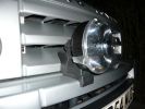
Part 1 of the LF Inset in Grill Installation221 viewsDetailes of the Grill preparation as well as the modifications needed to the front end.
|
|

gvif scheme79 viewsSchema for gvif installation using reversing camera, wireless caravan camera, hitch camera and camera select when driving forward direction
|
|

Discovery III Multimedia Installation v1.1159 views
|
|

Discovery III Multimedia Installation v1.2187 views
|
|
310 views
|
|
286 views
|
|
290 views
|
|
303 views
|
|
273 views
|
|
310 views
|
|
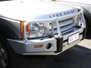
ARB Bull Bar Installation, Front side view. Colour coded to Vehicle.295 views
|
|
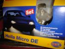
Hella Micro DE installation to S model Disco290 views
|
|
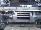
Close-up front view of partially-installed winch120 viewsNote that the sheet-metal flange just above the winch had to be notched to allow winch controller to be actuated. Also this same bracket had to be bent upwards to allow the winch hydraulic:electic solenoid to fit without rubbing. The nut on the upper-left bolt (the one with a very faint circle around it) stripped on re-installation, so the tray and winch pulling load is held only by the threads on 7 bolts....
|
|
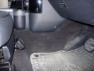
SmartNav speaker & button installation507 views
|
|

DVB-LR Installation Instructions Pages 1-440 views
|
|

DVB-LR Installation Instructions Pages 5-837 views
|
|

DVB-LR Installation Instructions Pages 9-1356 views
|
|

Thread upload2 viewsImage uploaded in new thread
|
|
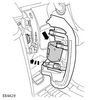
160 views
|
|

GOE Sensor Rod Installation12 views
|
|

FBH GSM Kit Installation Guide61 views
|
|

GVIF Manual64 views
|
|

gvif install89 views
|
|

Curt Manufacturing Installation instructions Class III339 viewsThese are the instructions for installation of the Curt Hitch.
|
|

iPod aux connection14 viewsPictures of installation of iPod into d3 cd player
|
|

iPod connection11 viewsPictures of plug pins break in solder and finished installation Jack lead iPod connection
|
|

iPod installation9 views
|
|

Webasto TC4 Pre-installation check23 views
|
|
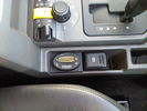
Oval Timer Installation44 views
|
|
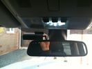
Blackvue Installation47 views
|
|

460 viewsPrevious installation.
Only my GPS, Mobile and MP3 changer in the back (controller seen on later pictures)
|
|
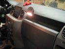
433 viewsA glimpse of the final installation, with a working map-reading light. In case the GPS doesn't work ;p
This is an old picture as the touchscreen is removed already.
However, I kept the reading light.
|
|
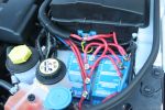
960 views'Rotronics' 3 stage battery management system installation
|
|
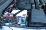
951 viewsAuxillary battery installation
|
|
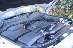
Towing/Dual batttery installation613 views
|
|

This is a night photo of the completed installation. The controller and screen brightness can be adjusted.499 views
|
|
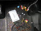
Installation64 views
|
|

Thread upload31 viewsImage uploaded in thread 92518
|
|

26 views
|
|

KDB500010 D3 Fire Extinguisher2 viewsInstallation instructions for D3 fire extinguisher.
|
|

Thread upload11 viewsImage uploaded in new thread
|
|

L319_MK4_ALTOX_GSM_remote_control_installation_manual37 views
|
|

OSRAM DLR/FOGLIGHT Installation Manual27 views
|
|

relocation of stuff to allow gigantic battery installation. The hood/bonnet barely closes wihout trouble.381 views
|
|

Land Rover Brake Light switch XKB5001102675 viewsThis is what the switch looks like when removed from the parts box. Note that the plunger is recessed back into the body and when installing, the process of rotating the switch body 1/4 turn anticlockwise releases the plunger so it pops longer and engages the brake pedal. If you look down on the plunger you can see curved slots where the rotation takes place.
Do not try to rotate the new one - play with the one you remove. Also do not press on the brake pedal when removing or installing as you will damage the plunger - this is one of the reasons the plunger is retracted into the body for installation. It is also for this reason that if you try to confirm the operation of the switch contacts with an ohm meter by pressing the plunger, the switch will appear not to function as one might anticipate. Have faith, the switch will however, once installed and the plunger is in full motion.
|
|

Rosen A10 Land Rover Installation Manual831 viewsThis is a 11 page pdf which is the Land Rover version of the A10 installation manual for our 3. It consists of a hundred plus sketches showing how and where to connect various cables, conductors and plugs.
|
|

LTB00105 - Technical Bulletin - Steering Gear Removal and Installation63 views
|
|

LTB00207 - Technical Bulletin - Body Side Molding - Installation Procedure59 views
|
|

LTB00293 - Technical Bulletin - Fuel Tank Availability Installation140 views
|
|
Thread upload2 viewsImage uploaded in new thread
|
|
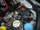
warn winch controller installation607 viewsremotely installed due to space limitations, and to keep the unit dry. Left Hand Drive, fitted in engine bay near washer fluid fill for reference point.
|
|
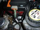
warn winch controller installation541 viewsremotely installed due to space limitations, and to keep the unit dry. Left Hand Drive, fitted in engine bay near washer fluid fill for reference point.
|
|
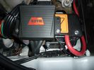
warn winch controller installation566 viewsLeft Hand Drive, fitted in engine bay near washer fluid fill for reference point.Remote control unit fitted on the box. Remotely installed due to space limitations, and to keep the unit dry.
https://www.facebook.com/DifferentialPartsUS
|
|
rear socket install1387 viewsTraxide rear socket installation, alternative location. These holes must be precisely in this location because there is little clearance to the right of left due to the blower motor and hoses, etc.
|
|
rear socket installation complete635 viewsThis demonstrates the rear sockets installed, shows how the sockets in use are tucked up nicely and out of the way.
|
|
rear socket installation complete671 viewsdemonstrate a neat and roomy install
|
|
D44 Winch stainless fairlead654 viewsThe completed D44 winch installation, including the stainless fairlead. A stainless trim plate, and NA license plate holder is on the way.
|
|
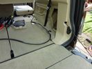
Traxide installation - rear cable19 views
|
|
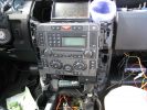
329 viewsInstallation slowly proceeding. You can see the controller cables inserted into the notch I made with a dremel.
|
|

Yanav PX3 Tesla Style Screen Installation63 views
|
|

Rosen A10 Manufacturer Installation Manual759 viewsThis is a 30 page pdf from Rosen that explains how to install the A10 unit. It is Generic in nature and hence carries detail not found in the LR specific install instructions. It also uses words and pictures instead of just pictures, hence can be a bit easier to figure out, particularily if you wish to take advantages of some of the hidden features not described in the LR material.
One of these features is how to hook up to a headrest display or I suppose even to the NAV in front.
|
|

SideSteps Installation Instructions495 viewsLR Official fitting instrutions for LR SideSteps
|
|

STC8138AB Generic Land Rover Fire Exinguisher4 viewsInstallation instructions for generic Land Rover fire extinguisher.
|
|

Toe link removal and installation124 views
|
|
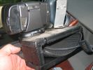
UHF Head Installation103 viewsThe unit is made from 16 mm craftboard. Screwed and glued together. A tight fit. A little silastic to help keep it in position.
|
|

VE 1.31 - Installation errors31 viewsVE 1.31 - Installation errors
|
|

VPLAS0041 D4 Fire Extinguisher4 viewsInstallation instructions for D4 fire extinguisher.
|
|

VPLAT0136 Towing Electrics Installation Manual31 viewsVPLAT0136 Towing Electrics Installation Manual
|
|

Thread upload1 viewsImage uploaded in thread 181177
|
|

Mechatronic Sleeve Removal and Install Instructions1043 viewsThis 3 page pdf with pictures shows how to remove and install the Mechatronic sleeve that tends to leak tranny oil after about ten years. Even if not leaking, replacement when doing a pan/filter change at the ten year mark is suggested.
Note the 3mm or less requirement when sleeve installation is completed; also that rotation of the sleeve during the install procedure can do damage to some internal pins - hence do not rotate the sleeve when trying to insert it or in getting it to lock in place - not so easy it seems.
|
|
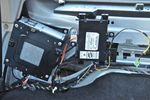
Completed installation33 views
|
|
|
|