| Search results - "installed" |

0000 LR Bluetooth dealer Kit install instructions1583 viewsThis 17 page pdf is mostly a series of pictures showing how to install the original Land Rover dealer installed Bluetooth kit for circa 2005 / 2006 three's. Also included are three wiring diagrams sheets related to the pairing code 0000 Bluetooth install.
This pdf is useful if you are now removing the 0000 kit to install the optical 2121 MOST D4 module, an easier install than the 0000 kit ever was.
|
|
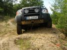
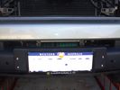
Here it is - long awaited Mantec plate in action directly after being installed! Thanks again John!!!169 views
|
|
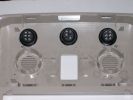
195 viewsSwitches installed in the roof panel
|
|

234 viewsThe cable loom for the lights (installed by 10forcash)
|
|
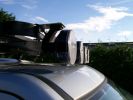
261 viewsOriginal Frontrunner brackets, but installed upside down to reduce the total height
|
|
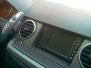
Geosat2 GPS installed498 views
|
|
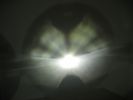
This is a normal H7 HID bulb installed in a BMW headlight to show glare above cut off line96 viewsThis is what the light pattern is that causes glare in most retofit applications including some projector lights. this is in fact a projector headlight on a BMW but the old projectors were only actually half projectors and half reflective bowls. the beam pattern should be clean cut like this ___/
|
|
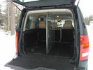
TravAll Dog guard installed and waiting for passengers163 views
|
|
new parts waiting to be installed2 viewsImage uploaded in thread 177818
|
|
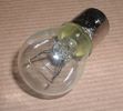
Land Rover Stop Tail Light dual filament bulb nominal 12 volt 21 / 5 watt filaments1412 viewsThis is the Land Rover part number 264590 dual filament bulb, (P21/5), that inserts into the upper two tail lamp receptacles. In the upper one, both filaments function, in the lower one, only the 5 watt tail light filament functions.
I regard it as not a good practice to routinely switch bulbs when the tail light filament, (5 watt), burns out on the lower bulb. The broken filament can jiggle over onto the brake light filament, (21 watt), and short the circuit to ground or something else not predicable.
There are also arguments to say that quality control is better on the Land Rover marketed bulbs than say far east sourced bulbs. Filament construction, and hence resistance can vary and mislead the current sensing circuits monitoring the signal light systems. Also when the bulbs are properly installed, all filaments should be standing vertically and not at any slope.
These are the sort of obscure circumstances that can lead to false trouble messages on the display, dropping to the stops, and subsequent concerns - all over a tail/signal light bulb.
For example, the filament life of both the tail light and the brake light filaments in the P21/5 bulb is significantly less than the USA common 1157 dual filament bulb, (1000/250 vs 5000/1200 hours); brightness in the P21/5 is a bit more, (3cp/35cp vs 3cp/32cp where cp is candle power), but current consumption is oddly less, (0.44a/1.86a vs 0.59a/2.10a where a is amps). It is the quest for efficiency vs maintenance trade off.
|
|
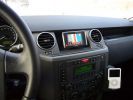
Navi Becker and iPod285 viewsThe Becker Highspeed II was installed in the bin with power connected. Works great, even TMC worked inside the garage right away!
|
|
Thread upload2 viewsImage uploaded in thread 187641
|
|

Land Rover Aerial Fin images for both Glass and Metal Roof Disco3 / LR3850 viewsAs well as the two different fins, this pdf also shows the plastic blanking plate for glass roof vehicles where no fin is installed.
The glass roof fin is secured by two security screws from the top into a plastic frangible glue on gasket. The hope is that when struck, the fin will shear off and not crack the glass roof. Re the metal roof design, the fin is secured from underneath via two nuts.
The pdf also shows the various electrical bits related to the antennas. In the UK, the fin would house not only a cell phone antenna but the TV and satellite radio antenna electronics as well; in the States, the Sirius sat radio antenna and a G type cell phone antenna if the phone kit was installed would reside within the fin. The SAT NAV GPS antenna is located within the High Mount Brake Light plastic mounted to the upper rear hatch.
|
|

Fin cell phone aerial drawing190 viewsThe factory aerial for the factory NAV / GPS on my 2005 HSE is within the high mounted stop light lens at the top of the upper hatch door. I do not have the factory installed phone kit, and as such, do not have the fin installed; instead there is just a plastic blanking insert to fill the cell phone aerial wiring hole in the metal portion of the roof; hence this requirement for an "external" cell antenna. For those that do have the fin on their glass roof, the fin is screwed on to a glued on plastic gasket, (sort of), and not bolted thru as per the metal roof 3's.
|
|
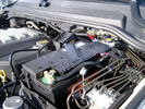
BCI Group 40R Deka 640RMF battery showing vent hose run forward to windshield washer reservoir area 1424 viewsRecessed post "Euro profile" battery to "match" OEM and stock Land Rover bracket; note that the Traxide SC80-LR module is mounted at an angle to allow for the main cable to sit under the cover so cover still closes.
The battery is a nominal 7", (180mm), high, but sits on a 1" battery spacer set under to raise the bottom front end of the battery such that the approx 11", (290 mm), length of the BCI 40R battery rises above the angled plastic nibs at the forward end bottom of the case front; hence sufficient space, (1/4", 5mm) remains at the brake reservoir end.
Also the 40R battery does not have hold down "flanges" on each end; on the sides yes, but not the ends so no additional length is required.
When I had to replace the 40R, this time I installed the shorter, (9.625"), taller, (7.5") Interstate BCI 47 / DIN H5 battery which eliminated the spacer on the bottom and better fit the stock LR tie down bolt lengths. Deka also has a BCI 47 / DIN H5 that would work fine as well.
|
|

D4 Auxilliary or Second Battery installed in Aux Battery Box214 views
|
|
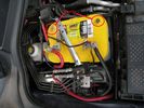
D4 Auxilliary or Second Battery installed in Aux Battery Box, Vents Circled188 views
|
|
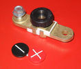
Battery Disconnect side post with + & - caps, top view616 viewsThis disconnect is designed for side post batteries. It can be used on either the + or - terminals. It can also be installed at the "other" end of the battery cable as well. In my install of the Aux battery, I installed this on the negative ground cable where the cable attaches to the body sheet metal. I have never used it but it seemed like a good idea at the time. The main battery hookup is pure stock.
For the hot side of the Aux battery, an Anderson PowerPole was used inline for the cable between the Aux and connecting to the spare bolt hole at the + post of the Main battery cable.
|
|

Black Deposits on Brake Light Switch Plunger2730 viewsThis jpg I got off another forum and is typical of what one will see when one opens up the removed brake light switch. The black powder is residue from arcing of one of the pair of contacts within.
Hopefully the newer switches with the FOMOCO logo moulded into the plastic are improved from the Land Rover logo marked early units, however I doubt it.
The Ford part number is SW-6572 and/or 7E5Z-13480-A as used on the 2006 to 2009 Ford Fusion's and Mercury Milan's; the Land Rover part number is XKB500110. Cost of switch could be about twenty five dollars. A previous LR part number for the switch was XKB500030, so hopefully the newer LR part number, XKB500110, reflects some improvement in reliability.
It is possible that the new switches are better as I installed a replacement 72,000 km, (45,000 miles) later, at 195,000 km (121,000 miles). When I took the removed switch apart to inspect, it was clean inside. There was no black dust - the switch looked like new, hence they must be improved now.
|
|
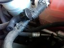
Breather line with factory cap cut off.2275 viewsIf you expand the jpg by clicking on it, in the bottom right corner if you look closely, one can see the black plastic factory vent tubing with the OEM cap cut off.
Note the tubing is cut at a 45 degree angle facing to the rear. Also shown in the top right is the cut off portion sitting on the coolant water hose and on the top left also sitting on the coolant hose, the new to be installed Gore manufactured replacement breather cap.
|
|
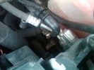
Breather Cap Installed1970 viewsThe black L shaped tube is is the Gore manufactured, (the Gore-Tex people), LR4 Breather Valve installed in an LR3. Naturally the installation looks similar to what one sees on an LR4 or RRS as the Gore breather valve is now OEM for new production.
The part number of this upgraded front differential breather valve is LR019450 and costs about thirty dollars.
|
|
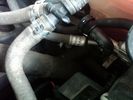
New Breather Cap installed.1674 viewsThis shows the new Gore brand angled breather cap installed. The cap points rearward to the firewall. Also shown is the cut off piece.
The new Gore breather cap is what one now sees on the LR4 and RR Sport.
|
|

109 views
|
|

338 views
|
|
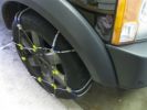
Snow Chains Installed - Land Rover LR3HSE94 viewsSnow Chains that seem to fit a Land Rover LR3HSE
|
|

Cubby fridge installed in 10 minutes44 views
|
|

Installation completed67 views
|
|
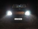
D4 hid kit installed and outside in the dark 6000k conversion.284 views
|
|
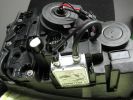
D4 hid installed in light ready to go213 views
|
|
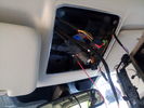
Wires installed for roof console122 views
|
|

Deka Battery Dimension Data613 viewsThe battery size that I installed for my auxiliary was a BCI 40R battery as it was for me the easiest to fit and was also a cranking battery. The case profile was such that no tie down fins were located on either bottom end, (sides yes), and length wise, it was only about 11" (290 mm) long. As such, I did not have to grind the nibs at the front bottom of the plastic surround.
I did however raise the bottom of the battery above the angled nibs as I set the battery on a 1" (25mm) high plastic spacer. The total height, (battery plus spacer), was about 8" (200mm) so the battery top still fit under the Land Rover factory cover.
For the Aux battery, when I replaced the 40R, I installed an Interstate BCI 47 which is similar in size to a DIN H5. I was therefore able to eliminate the vertical spacer as the Group 47/H5 is the same height as the DIN H7/H8 stock LR spec starting battery. As such, the standard battery tie down bolts can be used without modification. The Group 47 battery is 9 11/16" long x 6 7/8" wide x 7 1/2" (190mm) high.
|
|

Headlight mod and D4 grill mod62 viewsFirst tackle of mods to my D3, First attempt was the D4 grill, then the de-orange of the headlands, Also installed LED sidelights and indicators
|
|

UHF Radio installed20 views
|
|
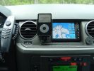
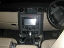
I-Pod installed into my Disco 3451 views I-pod video and Geosat2c installed. No visible damage to the deskboard, no holes etc.
|
|
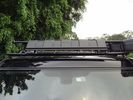
Wind Deflector for Rack14 viewsRecognise this part? Its the lower front recovery point cover. Installed upside down to silence the wind "drone" on the roof rack - works a treat!
|
|
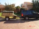
new conquest on the way to get the LR wheels installed203 views
|
|
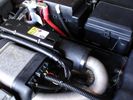
BAS FBH Controller Installed 188 views
|
|
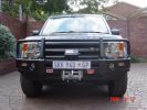
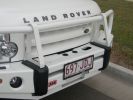
ARB333 viewsARB Bullbar and Warn tabor winch, with detachable tow ball(not installed).
|
|
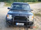
Smoked stripe on the windscreen438 views Installed 5 % foil into windscreen to hide the rear mirror tft lcd display a bit from the possible thiefs.
|
|
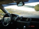
Rear mirror with LCD TFT display installed459 views
|
|
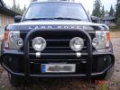
Driving lights installed432 viewsinstalled with Defender styled alu parts
|
|
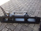
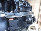
Hidden winch mount with winch in place122 viewsHydraulic hoses are now installed. Note notch for hydraulic:electric solenoid to fit in mount.
|
|
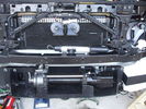
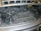
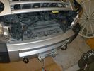
Front bumper view of semi-installed winch118 viewsNote the left-side (looking forward) bracket holding the white windscreen washer bottle.
|
|
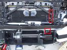
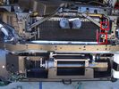
Installed winch with hydraulic hoses175 viewsThe hydraulic hoses are stiff, so I had to run them up the side of the radiator (can just see inside red boxes) to near the top of the radiator, then back down inside the engine compartment, then underneath the engine (behind the radiator) to the D4's power steering rack, where the hoses become metal. This hose routing may not be possible if the fuel-burning heater is in place (we don't have those in Aust and the space allowed room for my hands to bend and run the hoses without kinking).
|
|
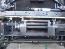
Close-up front view of partially-installed winch120 viewsNote that the sheet-metal flange just above the winch had to be notched to allow winch controller to be actuated. Also this same bracket had to be bent upwards to allow the winch hydraulic:electic solenoid to fit without rubbing. The nut on the upper-left bolt (the one with a very faint circle around it) stripped on re-installation, so the tray and winch pulling load is held only by the threads on 7 bolts....
|
|
Front-right view (looking forward) of partially installed winch and mount122 viewsThe closest bracket, with three rubber grommets, is the air bag sensor. Before beginning any of this work, be sure to disconnect battery and discharge any remaining electrical power. I didn't want to accidently drop this assembly and cause the airbags to deploy.
|
|
Installed winch with electrical solenoid connections158 viewsI routed the electrical supply (2 small wires) up the side of the radiator. You can see the unconnected wires inside the red boxes. I ended up connecting them on the radiator diagonal strut with cable ties. They are out of the way for any deep water transits there.
|
|
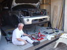
Installed winch, with bumper partially re-installed202 viewsPutting the D4 back together. Shows the tools and owner lying about.
|
|
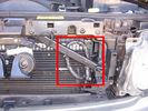
Installed winch electrical wires146 viewsWires which only power the solenoid are inside spiral wrap. They are also connected inside the wrap at the high point of the loop. Cable tied into place to prevent vibration rubbing.
|
|
Winch as installed176 viewsLicence plate is held on by winch cable and 4 metal pins which fit into modified bumper body. Winch rope is green
|
|
271 views
|
|
DVD Installed175 views
|
|
139 viewsbracket installed into existing mounting holes for coolant reservoir
|
|
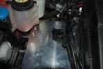
120 viewsThe plate installed on top of the bracket
|
|
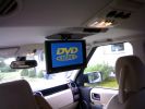
10.2" DVD player installed519 views
|
|

Rosen 7500s installed123 viewsrosen 7500
|
|
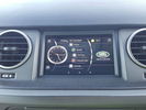
The Tablet Installed 15 views
|
|
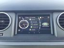
The Tablet Installed 26 views
|
|

Fluid, Filter/Pan Combo removal and install5947 viewsThese are the LR instructions re removal and install of the plastic pan/filter combo for the ZF 6HP26X transmission on the 4.4L petrol V8 LR3.
The instructions tend to ignore the reason you have to lift the right hand side of the engine about 40 mm. This is because of a frame cross member that interferes with dropping down of the plastic pan. The real problem is a vertical "oil filter spout" that rises out of the filter/pan combo up into the transmission. The spout is the suction pipe for filtered transmission oil back up into the tranny.
On the metal pan versions, the filter is separate from the pan, hence the filter remains with the tranny when the metal pan is dropped. The filter is then removed or installed independent of the metal pan, hence with the metal pan, there is no need to lift the engine.
If one is removing the plastic pan so as to install the metal pan, then some do not lift the engine but just drop the plastic pan enough to gain access to saw off the vertical plastic spout - it is a one time procedure.
Be aware however that the metal pan uses a flat gasket and the plastic pan uses a O ring like perimeter gasket that sits in a half round groove in the tranny casing. Also the metal pan uses 21 shorter torx M6x22.5 metric cap screws for the perimeter bolts. The plastic pan uses longer M6x28.5 torx metric cap screws.
|
|

Thread upload1 viewsImage uploaded in thread 198799
|
|
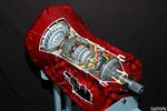
Ford 6R60 six speed cutaway showing torque converter.2188 viewsThis is a cutaway of the Ford 6R60 six speed which is a Ford license built version similar to our ZF 6HP26 six speed speced on early 3's.
The newer 3's and 4's have the ZF 6HP28. The Ford version is called the 6R80 and variations of it are used on the Raptor. As such, the Raptor metal pan can be installed on the 3's tranny but the deeper Ford Raptor pan does not have a drain plug.
|
|
Thread upload8 viewsImage uploaded in thread 130828
|
|
Thread upload6 viewsImage uploaded in thread 136532
|
|
Thread upload7 viewsImage uploaded in thread 130828
|
|
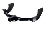
Curt Manufacturing brand hitch, assembled but not installed.282 viewsThe Curt Manufacturing hitch is an alternate to the Land Rover removable "plow" hitch. Once bolted in place, the Curt hitch is always there.
The Curt part number is 13456. It is a Class III hitch with a 2" square receiver and designed for a maximum 600 pound tongue weight.
The hitch hangs below the rear bumper but does not stick out past the bumper; also the "donut" spare tyre can still be installed / removed; am not so certain about a full sized fully inflated spare.
|
|
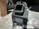
Rhino Tow Loop Hitch263 viewsThis is a receiver end view of the Rhino Hitch that ties to the factory tow loop. In addition to improved strength, it does not reduce ground clearance as does the factory style when installed.
Land Rover in early advertising videos when the 3 first came out showed the D3 hanging from a crane via the frame. The intent was to show how strong the frame is and by inference, the rear tow loop, specifically noted as being good for 6 tonne. The video ends before anything dropped or was lowered back to the ground, so one of course does not know for certain. The Rhino Hitch design however picks up on the apparent evidence of strength and certainly the additional clearance.
|
|
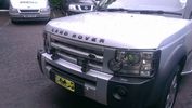
front of D3 with DS2 installed70 viewsPair of Rigid DS2
|
|

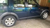
Side protection bars installed.48 views
|
|

Before side protection bars were installed.39 views
|
|

Mud flaps installed.39 views
|
|

D4 battery tray installed34 views
|
|

Traxide SC80-12, D4 tray and Optima D34 installed41 views
|
|

Close up - Solenoid14 viewsA close up of the solenoid which is installed close to the auxiliary battery bay.
|
|
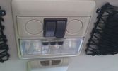
The on/off switches of the multimedia headrests14 viewsThese switches were installed to power on/off the previously installed gamecube and the screens attached to it.
When I removed the gamecube and lately the screens as well, I was clever enough (surprised as well) to leave the switches and all the wiring that I had running around.
They came in handy when I installed the multimedia headrests and are now adding an extra power on/off control of the screens.
|
|
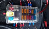
Fuse box in the rear12 viewsI installed the fuse box in the rear. Since I do have a 5-seater, there's plenty of space in the booth beneath the 2nd cover, which rests behind the second row seats.
|
|
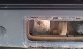
Outside connection to the compressor14 viewsFrom the compressor which is in the booth, the air hose runs to the back of the car.
I was able to install the connector in the space of the second trailer plug (which wasn't installed anyway).
|
|

President Johnson II in its current position16 viewsThis CB was installed some years ago and still is at the same location.
However, I'm planning to move it to the head unit area.
As such, I'm looking around to replace my low end head unit with a single DIN radio and the CB on top of it.
|
|

60 viewsFinal setup, everything in place after about one full day of work, which included removing quite some bits I had installed before.
|
|

DRL Loom Installed12 views
|
|
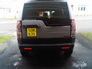
D4 Lights Installed121 views
|
|

first Headrest installed 62 viewswork in progress
|
|

A pillar mount installed166 views
|
|
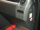
461 viewsFirst step in the journey, installed USB ports.
At the time I installed these, the goal was to use them in combination with the car-computer that resided in the back.
In the meanwhile, I dismantled the car-computer and nearly everything that was connected to it (touchscreen front, Wifi, DVB-T ...).
I kept the USB outlets in the front and turned them into charger for the appliances missus brings with her when we're on holiday. Mainly her iPod and smartphone ...
|
|

471 views@ home, we have 2 remote controlled garage doors. So I installed the remote controller in the car, added 2 buttons and off we go. Lucky me the controller worked at 12V anyway :D
I'll add a LED onto that one, so I'm sure it works when I press :)
|
|
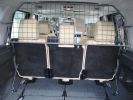
Paddock dog guard view from rear283 viewsInstalled; can see the mounting points
|
|

Newly installed Freelander2 headrest monitor9 views
|
|
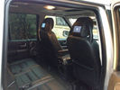
New Rear Seat Entertianment System newly installed15 views
|
|
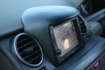
VMS & custom binnacle94 viewsVMS system and custom-made binnacle installed where LR factory satnav screen would be fitted.
|
|
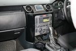
Centre console in black62 viewsnew mount installed for tom tom, thanks to Brucey for the use of his skills
|
|

This is where my iPod will live, unless I need to take it out to add songs or update playlists.491 viewsI installed a rubber grommit between the cable and the hole to keep it from rubbing on the sharp plastic.
|
|

airbox with EGR blanking kit installed 16 views
|
|

install in footwell13 views
|
|

Thread upload25 viewsImage uploaded in new thread
|
|

Thread upload6 viewsImage uploaded in new thread
|
|
Thread upload7 viewsImage uploaded in new thread
|
|

Interstate Battery Dimension sheet640 viewsThis sheet is hard to find - the sheet is not on the Interstate corporate web site but some dealer web sites display it. The pdf shows most of their available batteries including the H7 and H8 sizes that are the LR North America replacement batteries for the main starting battery. These batteries are of the Land Rover desired "shallow" cycle high discharge current Maintenance Free, (Ca Ca), internal construction, (not AGM, but instead, Wet Flooded Lead Acid with battery "caps" and Ca grid separators).
For the AUX battery , the H6, (BCI Group 48), is probably similar in dimensions to the Varta E12V75N that is popular in Australia. For that battery to fit in the second battery compartment, you must grind out the angled nibs on the inside front bottom of the LR black plastic surround, something I did wish to do and hence installed a Group 40R on a spacer. Alternately, one can choose an Interstate BCI Group 47 which is similar to a DIN H5 for the AUX location. I did this when I had to replace my 40R. No vertical spacer is required and the stock battery tie down bolts and clamp work well.
|
|
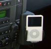
iPod cradle234 viewsThe dealer used the phone fitting and the iPod was installed via cinch connectors. Volume is controlled via the audio, charging function also included.
The sound even with the basic Audio system is terrific!!!
|
|

Replacement switch from RRS installed on LR3861 viewsThe switch shown is LR part number YUZ500020, the upper rear hatch release switch that is found on the Range Rover Sport.
The switch body is the same switch as on the LR3 except that there is no wiring disconnect on the LR3. Hence when the switch corrodes and requires replacement, the LR solution is to purchase a new handle and license plate light assembly. I instead cut off the old switch and installed a JAE mating connector to the existing wiring and hence just plugged the RRS switch in.
The replacement RRS switch snaps into the same rectangular space in the same manner as the removed LR3 switch, the difference is the JAE male wiring connector.
|
|
JFC50098028 viewsMy current installed unit.
|
|
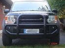
Installed nudge bar today322 views I was quite easy and quick to make. Took only 2 hours, easy job.
|
|

LA501-024 - Technical Bulletin - Dealer Installed Door Moldings61 views
|
|
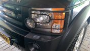
7 viewsLampguards front installed
|
|
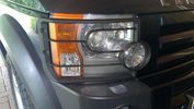
8 viewsLampguars front installed
|
|

Thermostat Housing LR005631527 viewsWhen the time comes to install a new thermostat, consider installing the whole housing instead.
Advantages are the thermostat is correctly installed, (not as simple as it should be); you get all new plastic and that is important, plus a new coolant temperature sensor and also a new heater coolant bypass valve, the secret part no one realizes is also within.
The cost of the whole assembly is not much more than the cost of a factory thermostat and the effort to replace all is not as difficult as it might seem.
|
|
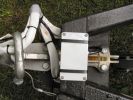
Here it is attached to the caravan "A" frame.631 viewsThe cable ties are temporary until I can drill and tap a couple of holes for screws.
|
|

LLumar AIR80 Air Blue 78 windscreen film IR reduction metal oxide339 viewsThis pdf summarizes the characteristics of the various types of window glass film available from LLumar. www.llumar.com
I had the Air 80 metal oxide sort of clear film, (windshield film they call it), installed on the front driver and passenger side windows to reduce the Infra Red penetration and hence heating effect on the front occupants. The film is barely visible from either inside or outside, however there is a noticeable reduction in heat penetration when sitting inside. In short, my arm does not get cooked.
Cell phone and GPS etc seem unaffected by the metal oxide film.
I also had the film installed on the three sun roof portions as well.
|
|
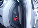
Air Suspension ECU Fuse 35P cut off switch.3802 viewsThis shows the SPST rocker switch mounted in the blank plate installed in lieu of a manual passenger side air bag shut down switch - now automatic via passenger seat pressure switch. Fuse 35P (5 amps) is located in the interior fuse box behind the lower glove box and protects the ignition power supply to the Air Suspension ECU. When the SPST switch is moved to the OFF position, the RAISE /LOWER switch on the centre console is not powered, and hence does not function. As such, some signals from the wheel height sensors and CPU are ignored. By itself however, removing F35P will probably not stop the 3 from self dropping, particularly after the engine is turned off.
Fuse F3E, (5 amps), located in the engine bay fuse box by the starting battery protects the circuit that provides feedback to the Air System ECU indicating that the Compressor Relay has successfully operated and that the Air Compressor is or should be operational, can also be removed, (but is probably not totally necessary), as it gets its power thru F26E. Hence Fuse F26E, (20 amp), also located in the engine compartment fuse box is the fuse that must be removed. This fuse protects the circuit that provides full time battery power to the Air System ECU. When in place, current thru the fuse powers the periodic re-levelling action, (usually lowering a bit with that brief air release noise), that often occurs when the vehicle is parked and the engine is off.
Removing F26E fuse will stop the auto levelling action and also inhibit any other down to the stops signals, (engine running or not). When F26E is removed, no power can flow thru to F3E, hence removing F3E is more for insurance than an absolute requirement. The same with F35P, removing F26E removes primary full time power from the Air Suspension ECU, and hence removing the F35P fuse should not really be required either as long as F26E has been removed.
|
|

Battery Maintainer pigtail sticking out of Grill723 viewsThis is all you see when everything is put back together - just the pigtail and Weather Pack blanking plug. Most often, I have it all tucked back behind the grill.
In winter, there may be a second cord hanging out as well - the 120 VAC power cord for the engine block heater, a tea kettle like element inserted in the engine block. NAS petrol V8's do not have the Fuel Burning Heater, (FBH), installed, but instead in cold area markets have the block heater element assembly available as a dealer installed option. There is an argument to say that the heating element is factory installed in all cold climate V8 gasoline engines, however the appropriate power cord is not. If true, this means that all one needs to purchase is the area specific power cord and plugging in / attachment to the engine block located block heater.
As such, you will often see a conventional 120VAC three prong power plug hanging loose out of the grill of most vehicles here in the wintertime. In summer, most drivers tuck the plug back behind the grill as it is no beauty mark.
|
|
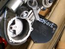
Compressor Con Rod Broken 1744 viewsThe model number of this compressor is RQG500060; the model number of my replacement compressor was LR015303, the unit that was apparently being installed on the D4 vehicles as of Spring 2010. As of Fall 2011, the new replacement part number is LR023964, the same as in the 4's.
Note the number hand written on the black plate. All the compressors seem to have some number hand written on them - hand built I presume, and every unit perhaps evolving a bit differently as LR struggles to build a compressor that will last. I guess Hitachi, (the manufacturer), should be given credit for that.
|
|
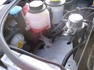
Empty space in NAS LR3 for location of FASKIT panel595 viewsThe empty space is available as the North America Spec gasoline engine LR3's do not have the Fuel Burning Heater installed. The air lines from the four air springs and the air tank will appear to rise up from under the headlight assembly. The lines to the front block valve assembly located behind the front right fog light will sort of run within the bumper across the front of the radiator down into behind the righthand fog light. The rear lines somewhat follow the path of the existing air feed line from the front valve assembly to compressor. Rather than be located between the left front fender liner and left metal wing however, the four lines will feed thru the empty wing space inside and above the wheel well arch and exit down by the left front mud flap. From there, the lines run along the left frame member above the air tank and then parallel the frame over top the compressor to the top of the rear left air spring where the rear air block valve assembly is located.
|
|
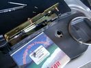
0.032" OD metal fishing leader and lead fishing weight clamped to existing wire rope 2104 viewsI used a size #0 lead fishing weight as a clamp to attach the 0.032" diameter flexible wire rope fishing leader to the release cable.
The pictured weight is the smaller #00 weight, however it did not work very well so reinstalled with the larger #0 size. I clamped to the cable as what breaks is the L retainer that is hidden in the actuator and holds the cable. When the L breaks, it lets go of the cable so you hear the clicking but there is no opening action.
Clamping on to the cable is an attempt to resolve that reality; also if the actuator electrically fails, the release mod should still do the task. Note in the picture the two Torx T15 screws that hold the gold plate to the plastic case and also the two 8mm cap screws that have to be loosened to remove the actuator from inside the door.
|
|

NAS 7 Pin Round Socket + 4 Pin Flat Socket oriented as installed.742 viewsThis is the layout you see when you look into the NAS Land Rover sockets as installed at the rear of the LR3/4. The flat 4 pin socket is located under the round socket.
Wiring order is relative to the slot on the round socket, and hence the same as the other jpg where the slot is shown at the top.
The CJB monitors the front and rear turn signal lamps and can detect if more than four lamps are fitted, (the side turn signal lamps are not monitored). This is another reason for using genuine LR bulbs as off shore bulbs can have varied and out of spec resistance values.
When a trailer is detected, the trailer warning indicator in the instrument cluster is supposed to flash green in synchronization with the turn signal indicators.
If one or more of the turn signal lamps on the vehicle or the trailer are defective, the trailer warning indicator will cease to flash any longer. This is to alert the driver to probably bulb failure.
If the trailer has LED lamps installed, and no LED adapter circuitry is used, most likely the trailer will not be sensed and systems such as the backup sensors will not be disabled.
|
|

Land Rover Brake Light switch XKB5001102675 viewsThis is what the switch looks like when removed from the parts box. Note that the plunger is recessed back into the body and when installing, the process of rotating the switch body 1/4 turn anticlockwise releases the plunger so it pops longer and engages the brake pedal. If you look down on the plunger you can see curved slots where the rotation takes place.
Do not try to rotate the new one - play with the one you remove. Also do not press on the brake pedal when removing or installing as you will damage the plunger - this is one of the reasons the plunger is retracted into the body for installation. It is also for this reason that if you try to confirm the operation of the switch contacts with an ohm meter by pressing the plunger, the switch will appear not to function as one might anticipate. Have faith, the switch will however, once installed and the plunger is in full motion.
|
|

LR 6HP26 transmission oil part number TYK5000501413 viewsThis jpg shows the genuine Land Rover transmission oil, part number TYK500050, for the 6HP26X tranny. The Shell product number is M-1375.4 but you cannot buy the oil retail from Shell. The container size is one litre.
A routine oil change where the pan/filter combo is not changed takes about 3.5 to 4 litres of oil. When the tranny is brand new, a dry fill can take up to 9.5 litres of oil however around 7 litres is more common for when a new pan/filter combo is installed on an already in service transmission.
|
|

How to cable factory BT module (including MOST bus connector)82 viewsInstructions to install Factory BT module in a Disco 3 that has LR aftermarket or no BT module installed
|
|
322 views
|
|
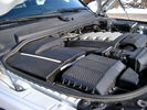
Overview of engine compartment from Main Battery side, (Passenger, LHD), looking across to Aux Battery749 viewsNote labels on main battery cover. The one you cannot read says that an auxiliary battery is installed on the other side. This is to warn service people should they wish to shut off all battery power.
The main starting battery is supposed to be of CaCa separator construction and DIN H8 or BCI Group 49 size. This means Calcium separators Wet Flooded Lead Acid, 13.9" long, 7.5" high and 6.9" wide.
On the Aux battery cover is a label saying to disconnect the blue Anderson single pole connector located under the cover by the brake reservoir. BCI Group 40R battery is small enough that the cover goes back on.
|
|
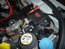
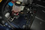
warn winch controller installation607 viewsremotely installed due to space limitations, and to keep the unit dry. Left Hand Drive, fitted in engine bay near washer fluid fill for reference point.
|
|
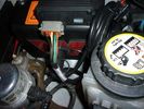
warn winch controller installation541 viewsremotely installed due to space limitations, and to keep the unit dry. Left Hand Drive, fitted in engine bay near washer fluid fill for reference point.
|
|
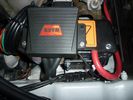
warn winch controller installation566 viewsLeft Hand Drive, fitted in engine bay near washer fluid fill for reference point.Remote control unit fitted on the box. Remotely installed due to space limitations, and to keep the unit dry.
https://www.facebook.com/DifferentialPartsUS
|
|
rear socket install825 viewsThis photo shows the rear sockets installed, shows how the sockets in use are tucked up nicely and out of the way.
|
|
rear socket installation complete635 viewsThis demonstrates the rear sockets installed, shows how the sockets in use are tucked up nicely and out of the way.
|
|
radar detector wires tucked up high424 viewsThe orange ties hold wiring sockets for floodlights (to be installed). Red tie holds excess wire for radar detector.
|
|
wires tied up tight539 viewsThe Orange ties hold wiring sockets for floodlights (to be installed). Red tie holds excess wire for radar detector.
|
|
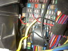
Fuse Panel showing F35P Add A Circuit installed1230 viewsFive amp fuse F35P is located towards the top left in this jpg. The other three Add A Circuit devices are for other items - powering my cell phone base etc.
Note the orientation of the Add A Circuit as this matters. Also one can just see a red tab sticking out from behind the device. The red is the conductor crimp end of a narrow 2.8mm male spade type connector that inserts into one of the "fuse" slots.
|
|
Thread upload3 viewsImage uploaded in new thread
|
|
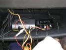
247 viewsThe two installed modules with preliminary wiring for testing.
|
|
camera installed in towbar cover.359 viewsthere is a plug on the power and video connector so can easily be removed for towing
|
|
camera all installed - same size as a sensor381 viewscant go in centre of panel due to towing hoop
|
|
Pioneer TS-SW1041D 10" sub installed120 viewsAfter cutting off the factory sub mount studs, it took ages to bash the indents. To gain more space behind the driver - I changed the driver\'s side license plate from plastic push in lug - to stainless bolt with nyloc nut. Cr@ppy paint job in wrinkle-finish - all I had on hand at the time. Sealed and treated lower tailgate with Dynamat.
|
|
New Rubber26 viewsToday my new Pirellis are installed.
|
|
Back view of Brodit holder with Ram 1" ball long arm installed27 views
|
|
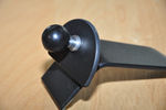
Modified D4 mount with ball installed26 views
|
|

Redundant Parts972 viewsThese are what you are left with once the EGR blanking kit is installed. Best to hang onto them in case you need them again!
|
|
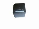
Front Blower R16 relay, part number YWB500060473 viewsThis is the front fan relay located in the engine compartment fuse box. It should be replaced and installed new when a new fan is installed.
|
|
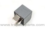
Air Compressor 70 amp replacement relay1384 viewsThere is a software update, 09 April 2010, LTB00270, for the compressor which reduces the shut down pressure to about 205 psig (14 bar). The update is usually done when changing to a new compressor and also includes replacing the R7 relay in the engine compartment fuse box, 07 DEC 2010 LTB00331.
The newer grey case coloured relay, part # YWB500220, shows to be rated at 70 amps, (the relay, not the compressor), however the previous black case coloured relay also indicates 70 amps.
Both the new and replaced relay show on their wiring diagrams to have a parallel voltage spike resistor, (probably 560 ohms), across the coil terminals, #1 and #2. This means one does not just replace the relay with any four prong 70 amp ISO sized relay that one happens upon.
One presumes the grey relay is either upgraded or just being installed for good measure. The relay is common on Ford Fiesta for the seat heater relay, Ford part number 5M5T 14B 192 EA; also Volvo, part number 30765034. The Tyco part number moulded on the grey body is V23136-J4-X62.
|
|
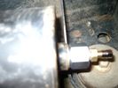
Reservoir Air In fitting installed 1648 viewsSchrader valve installed. Shop air can now be introduced into the tank to facilitate the raising of the 3 when there has just been a failure of the onboard air compressor rather than the electronics or valve block wiring etc.
Air could also be sourced from this point, however the purpose of the modification is air in, not air out as the air pressure normally runs above 200 psig, too high to be safe for routine use unless a pressure reducing regulator is added per the Mitchell Bros kit.
|
|
Reservoir Air In fittings exploded view 1885 viewsThis shows the fittings required for the mod. The reducer adaptor requires a 27mm socket and is M20 x 1.5 male thread x 1/4" NPT female. The 1/4" male NPT Schrader valve has the standard valve core removed and an AN/MIL spec aircraft oleo strut valve installed instead.
A standard automobile valve is rated at 200 psig, (14 bar); the air tank runs closer to 244 psig, (16.8 bar), with the relief valve set to open between 334 psig, (23 bar) and 370 psig (25.5 bar). The aircraft valve is rated at 2,000 psig, (138 bar).
|
|
Reservoir Bung 24mm socket 1149 viewsThis is the view of the air tank at the end nearest the front left wheel. This is what you see before you do the mod. The other view is after the mod.
On pre 2008 models, there is this 24mm socket hex head bung, M20 x 1.5 thread, that can be unscrewed and the Schrader valve assembly installed instead. On newer 3's the bung hole was deleted from the front end of the air tank; hence the mod as described, is then not possible.
|
|
Rhino racks installed!215 views
|
|

RAI installed183 views
|
|

Rosen Owners Manual879 viewsThis 28 page Owners Manual is the Rosen version written specifically for the A10 model DVD Video Game Entertainment System player that may in attached to the roof of your 3.
Discussed is how to use the remote control, the wireless headphones, the TV feature if installed, and how to change from 16:9 widescreen format back to the older 4:3 format.
|
|
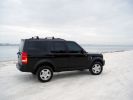
At the beach462 viewsInstalled the rails to bring home the Christmas tree. Installed them myself & quite proud of that fact since I\'m not the mechanically inclined type hehe.
|
|
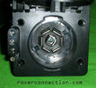
NAS 7 pin + NAS 4 pin Flat Trailer Socket304 viewsThis is the vehicle end of the NAS trailer harness that is located behind the removable plate centered within the rear bumper by the towing loop. Re the four pin flat connector, from the bottom, the exposed bare lower pin is the ground, usually the White wire on a NAS trailer. The next pin up is normally a Brown wire on a trailer and is for the Tail Lights. The third pin, normally a Yellow wire, is the left signal light; the top pin, normally a Green coloured wire, is the right signal light.
Re the round connector, from the notch in the plastic surround, clockwise, the first blade is ignition controlled +12VDC battery power, (only alive when engine running), and on the Land Rover factory harness is an Orange wire; on a NAS trailer, usually Red but perhaps a Black wire.
Next blade clockwise at 3:00 o'clock above, is the Right Turn signal light, a Green wire on the LR harness, and also on a NAS trailer.
At 5:00 o'clock, the next blade is for the Electric Brakes and is Blue on both the LR harness and on a NAS trailer.
The Ground wire is next, White on both the LR harness and on a trailer.
At 9:00 o'clock above, is the Left Turn signal, Yellow on both the LR harness and on a trailer.
The last blade to the left of the line up notch is the Tail Light circuit. On the LR harness, the wire colour is Brown with two White stripes and on a NAS trailer, Brown.
The centre pin is for the Reverse Back Up lights and is Black on the LR harness and often Purple on NAS trailer wiring but can be Black also.
Note that when the socket assembly is installed on the 3, the notch in the plastic surround is on the left - that is rotated 90 degrees anticlockwise to the picture above. In other words, When installed on the 3, the 4 pin flat connector lays horizontal and is located below the round socket.
|
|
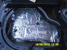
Sound insulation installed50 views
|
|
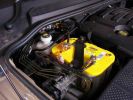
Aux Battery Installed1031 viewsIts a tight fit, but uses the LR battery mounts and bracket, slightly modified.
|
|
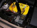
Installed and wired863 viewsShows the wiring loom to the isolator, the feeds (fused link) to the rear outlets and the other feeds are for the battery meter
|
|

150t Air Seperation column South Africa95 viewsShows us lifting a 150 tonnes 50 metres long, Air Separation Column in South Africa, we were responsible from UK manufacturer up to installed onto foundations in SA.
|
|
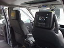
Dual Headrest DVD installed45 views
|
|

Sirius Radio installed overhead58 views
|
|

Side Shot664 viewsSliders and plastic wheel arch mud guard, not installed....
|
|

Thread upload17 viewsImage uploaded in thread 132186
|
|
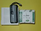
Upper Hatch Release Switch LR Part Number YUZ500020672 viewsThis is the Range Rover Sport switch, Land Rover part number YUZ500020, as it comes out of the box. Note the JAE, (Japanese Aviation Electronics), male wiring connector installed on the end of the power lead.
The rubber cover of the switch is sealed to the plastic body of the switch whereas in the previous switch design, there was no sealing. Also the replaced switch was hard wired into the same harness as the license plate lights - no JAE connector in other words.
|
|
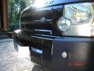
Fog lights installed409 views total costs were only 80 euros
|
|

UHF - install18 views
|
|

UHF - install17 views
|
|

UHF - tape17 views
|
|

Modified Wiring diagram for the added electrical bits25 viewsI made this wiring diagram during the cleanup I did lately.
I completely removed some 'old' electrical bits I had installed and used the occasion to document every left and new part.
|
|
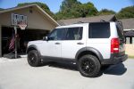
My LR3118 viewsafter new GY Duratrac's installed and modified rod sensors
|
|
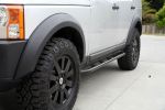
RS II Sliders128 viewsRover Specialties sliders installed (Off Roving)
type RS II slim line
|
|
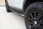
RS II slim line sliders119 viewsRover Specialties sliders installed RS II slim line (Off Roving)
|
|

Mechatronic Replacement Hints plus drains for steel and plastic pans1101 viewsThis 22 page pdf shows colour views of the Mechatronic unit as well as good illustrations of the drain and fill ports in both the plastic, page 17, and steel pans, page 18.
Page 8 details the replacement of the sealing sleeve where the electric wire feed thru the case into the Mechatronic unit. The seal is normally replaced when a new pan is installed as the seal is a known leakage point.
|
|
|
|
|
|