| Search results - "left" |
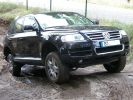
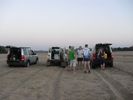
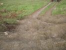
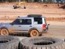
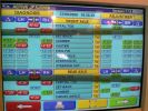
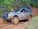
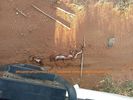
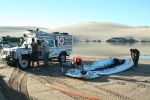
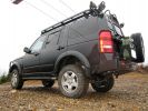
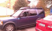
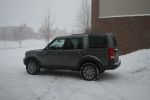
241 viewsThis Toureg is stuck - doesn´t look like it. After 8 hours of driving everyone agreed that with the big 10cyl. diesel engine you should probably oder the rear difflock as well... In this picture the rear left anf front right wheels have no grip, esp or whatever just doesn´t do it.
|
|
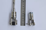
127 viewsleft hand adater adopted, decided right hand adapter was ok but right hand one fits and is stronger
|
|
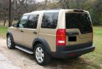
Left side view149 views
|
|
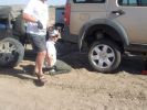
06 Spare tyre on and still suffering from hot wheel nuts296 viewsManaged to get ultra hot wheel nuts back on the spare (using the original 19" D3 wheel, vs the 19" RRS wider wheel which blew - shown in left of photo). Pity we didn\'t note that the disk brake was EXTREMELY hot at this time.
|
|

Who Left This Stick In My Car15 views
|
|

Broken roller rocker on left20 views
|
|

Should I go Left or should I go Right?81 views
|
|
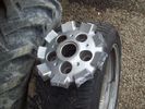
What was left24 viewsThe bitty which was left attached to the hub when the wheel failed whilst driving
|
|
Clear left140 views
|
|
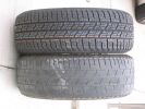
New vs. 15000 Km wear on the front left wheel476 views
|
|

15 First sign of bits of parking brake failure335 viewsNote the complete lack of pad from the parking brake. Not only was there no composite brake material left, but the drum was somewhat twisted and connecting bits all smashed. Also a small drip of melted rubber from wheel bearing parts....
|
|
led left133 views
|
|

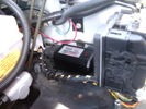
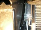
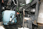
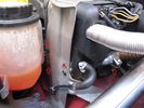
Whatissit138 viewsPicture of a thing in the engine bay, just to the left of the coolant bottle and just behind the edge of the radiator.
|
|

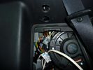
Inside the kickpanel4286 viewsRed = Left Channel
Blue = Right Channel
Black = Screen
|
|
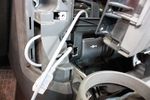
left side68 views
|
|
62 viewsCutout done, all that's left is to stuff the socket into the cutout
|
|

Audio control wiring loom LEFT16 viewsLeft Door wiring loom for audio controls
|
|

Rear left door audio control loom12 viewsRear left door audio control loom
|
|
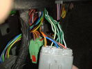
connector21 viewsLeft hand kick panel area
|
|
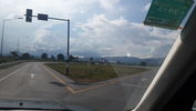
switch16 viewsthe point where you switch from right to left side road.
Laos is drive on right..Thailand left
|
|
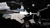
Left rear door1 views
|
|
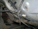
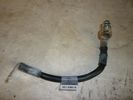
Left hand wheel sensors cable ends76 views
|
|
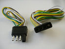
4 pin NAS flat connector from NAS small trailer377 viewsThe connector with the three exposed pins is the end that would commonly be located at the trailer hitch end, (front), of a small NAS lightweight trailer that has no electric brakes. This plug would connect into the flat 4 pin connector at the rear of the 3.
Note the order of the pin functions and wire colours: White is ground; the next pin is for tail/marker lights using the Brown wire; the Yellow conductor is for the left turn signal, and the far pin uses the Green conductor for the right turn signal.
There is no separate brake light conductor as NAS spec vehicles most often combine the brake and signal light functions to the same bulb filament rather separate filaments in different bulbs. The LR factory harness resolves that design difference.
Fortunately, the Land Rover NAS assembly pin order for the 4 pin flat plug maintains the above described conventions.
|
|
Thread upload8 viewsImage uploaded in thread 163691
|
|
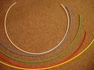
6mm Heat Shrink colours 362 viewsI decided to colour code the tubing so I used 6mm electrical heat shrink.
As there is no apparent colour coding re the 3, I tried to emulate the P38 coding; #1 LR red, #2 RR blue, #3 LF yellow, and #4 RF green. This was not doable as both left side air springs have green coloured tubing coming off the top of the front and rear air springs. I therefore arbitrarily chose the Left Rear to be red; Left Front green; Right Front yellow; Right Rear blue; and for the air compressor supply line, White coloured heat shrink. Since two new lines tie into each air spring line, I made the line between the air spring and the FASKIT, a single solid colour, and the line from the FASKIT to the valve block, White, plus the related appropriate solid colour.
|
|
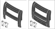
A-Bar Varients221 viewsWinch Version on Left / Non-Winch Version on Right
|
|
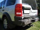
Rear left103 viewsDamage to car after ~60km/h rear end collision
|
|
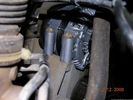
58 viewsOne bolt is visible at the front, but the other two are down the left hand side and best accessed by removing the small plastic guard behind the bumper. I also removed the small metal radiator guard between the bumper and the main sump guard (but that was mostly to retrieve the spanner I dropped!). The only issue with removing the plastic guard is the stupid plastic clips that hold it on may need to be replaced.
|
|
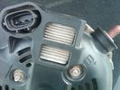
Alternator Plug and B+ terminal910 viewsPictured is the rear of the older Land Rover part # YLE500190 alternator showing the shiny cooling fin of the Regitar VRH2005-142 regulator under.
The first pin in the far left side of the connector is numbered #1 in the LR electrical wiring diagrams and is Battery Voltage Sensing (BVS); the middle pin, #2 receives a Pulse Width Modulated (PWM) signal from the Engine Control Module (ECM), and the right pin, #3 carries a PWM signal back to the ECM. Terminal Pin #2 on the LR wiring diagrams is called Alternator Control or ALT CON; Pin #3 per LR is called Alternator Monitoring or ALT MON.
Pin #1 is similar to what in older designs used to be called A or Batt, but is now called by Denso, S, AS, or Alternator Sensing for this design. Pin #1 also provides power to excite the alternator at startup until the PWM instructions over ride the battery voltage info. Land Rover calls the electronics under the pins a Smart Regulator, ironic, as it has to follow orders from the ECM rather than give the orders - new age thinking I guess. This is different from older design internal regulators that look at just the battery or the electrical buss voltage and then decides itself what to do.
It is almost like we are back to the external regulator designs of old, except that the ECM may decide that instead of telling the alternator to make more power, to load shed, and hence shut down the heated windscreen, seats, or whatever other electrical loads it decides are appropriate. My view is that the "smarts" are in the ECM and that the "regulator" should be regarded if not dumb, then as being a slave to the ECM.
|
|

95 views
|
|

Thread upload3 viewsImage uploaded in thread 144213
|
|

OLD VERSION - Bodsy's Brake Bible v 1.611086 viewsUSE Version 1.6a
Clarified EPB shoe instructions & corrected references to other sections. Added paypal donations information (requested by users of the guide.) Internationalised wheel location references by removing UK based reference to OS/NS, replaced with physical Front Left or Front Right descriptions.
|
|

crankshaft bolt22 viewsBolt on left is new one for upgraded oil pump casing. Bolt on right is what came out. Notice damaged end and shortness of bolt. Inside of crank was inspected wirh borescope and threads etc all ok. New bolt goes in and out ok. Few filings inside but otherwise clear. Not sure why old bolt ended up like that.
|
|

Black Deposits to interior of Brake Light Switch2831 viewsThere are two contacts, one on each side of the vertical plunger under the copper metal. The set of normally open contacts on the left side that carries the power for the brake light filaments, (15 amp fuse F15P), is apparently not heavy enough as the contacts deteriorate and generate the black residue.
The set of normally closed contacts on the other side appear to be sized OK. There is not as much current, (5 amp fuse F66P), flowing thru the contacts to the ABS module, however the contacts are likely adversely affected by the black residue produced by the other deteriorating set of contacts.
One presumes/hopes that the newer replacement switch now has contacts heavy enough to carry the brake light power. It would be ideal if the ABS set of contacts were sealed from the brake light contacts to prevent contamination of the normally closed set of contacts.
|
|
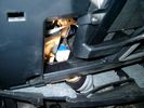
Brake Switch Visible thru Opening4933 viewsThe blue and white bit is the switch; the sort of gold appearing box,(it is really black), you will not see in your 3 as it is a Smooth Talker brand amplifier for my Blackberry phone antenna. This install is detailed in the SmoothTalker phone antenna section of my gallery.
One way to remove and install the switch is to lower the "horizontal" panel above the brake pedal as shown where the flashlight head is located. To actually remove the switch, you slide your hand thru the gap and rotate the switch clockwise 1/4 turn while watching thru the rectangular opening. Installation of the new switch is the reverse of above - 1/4 turn counterclockwise.
Before you remove the switch, note its orientation - horizontal with electrical wires to the left. That is the way it should look after replacement as well.
The second time I replaced the switch, I did it all thru the rectangular opening and did not remove the horizontal panel - that is experience helping out.
The knee kick you have to remove regardless. It is sort of hinged at the bottom so you just pull at the top and sort of rotate the knee panel and then pull upwards for two plastic "fingers" to clear the slots they reside in.
|
|
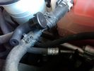
Breather line with factory cap cut off.2275 viewsIf you expand the jpg by clicking on it, in the bottom right corner if you look closely, one can see the black plastic factory vent tubing with the OEM cap cut off.
Note the tubing is cut at a 45 degree angle facing to the rear. Also shown in the top right is the cut off portion sitting on the coolant water hose and on the top left also sitting on the coolant hose, the new to be installed Gore manufactured replacement breather cap.
|
|

Thread upload3 viewsImage uploaded in thread 186650
|
|
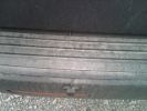
LH cable tucked under ribbed bumper plate160 views
|
|
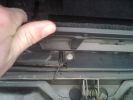
Detector Cable left158 views
|
|
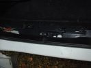
Rear passenger (left) wire harness channel41 views
|
|

Thread upload2 viewsImage uploaded in thread 182352
|
|
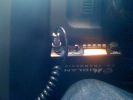
204 viewsCB location under steering wheel to left.
|
|
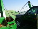
All at sea in an LR3103 viewsThe ferry from the mainland to Mazira Island was packed to the gunnels with vehicles. My LR3 was last on and they left the bow doors partially open for 14 lonnnnng sea miles across the Arabian Gulf!
|
|
Sundowners in Shashi River68 views3 Countries in 1 picture, Left is Zimbabwe, Right is Botswana and on the horizon is South Africa
|
|

Left to Rust81 views
|
|
Calendar 2008 Entry563 viewsLeft to right: Access Height, Off Road Height & Super Extended Mode
|
|
CounterAct Power Supply mounted 244 viewsPicture is blurred, however power supply is 3M two sided tape to the flat black plastic of the second battery compartment just under the antilock brake pipes to the fender side of the brake fluid reservoir. The white wire to the left rear coupler pad runs thru the firewall hole near the steering column. The blue wire to the right front coupler runs across and above the engine following the other wiring looms that cross the vehicle.
|
|

Not much left of bonnet!278 viewsCrash in a Renault Scenic
Head on colition with a Nissan Terrano he lost control came over the central reservation & ended coming at us sideways!
We hit him in the back wheel arch & spun him around so he then hit my drivers side, I walked away having a air bag wife had broken solder coursed by the seat belt, but it did save her life!
Our car was trashed but it did its gob (was only 2 weeks old!) the bonnet tacking lots of energy out of the collision & the inertia staying relatively in tacked.
|
|

ARB air compressor switch, gauge, outlet.312 views
|
|
Tyre Change44 viewsWhat a place to change a tyre! - See top left !
|
|
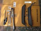
D4 Mantec Fitting Tools Required and bits left over at the end226 views
|
|
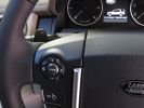
D4 left tip147 views
|
|
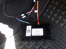
D4 Bluetooth AH42 10F845 AA module connected to 12VDC and MOST1190 viewsThis jpg shows the MOST bus connected to the AH42 10F845 AA module used in the D4 as well as +12VDC power from F58P connected. The power is split with a Y harness as the IHU (radio) for some reason required +12VDC power to the C2115-10 "mute" pin to keep the radio/CD audio from muting all the time.
With power on the pin, the radio audio does mute as it should when the cell phone rings and the hands free connects. The brown conductor feeds to C2115-10 and the blue to the module.
The module tucks up and hides behind the grey plastic section covering the forward portion of the passenger side tranny hump for left hand drive vehicles; for RHD, it would be located on the left side.
The pairing code is 2121 with this setup and not 1234 or 0000.
|
|
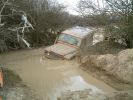
I said turn left you numpty42 views
|
|

D3 reqar diff lock181 viewsView from right rear tyre well, left rear tire/rim visible on other side. Actuator motor visible
|
|
stay on the left207 views
|
|

Ford at Great Alne - Warwickshire483 viewsGood long drive through here, a big drop into the start though and some deep water at the left on driving in, you can see me steer right to avoid!!
|
|

357 views
|
|
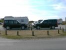
2 Discos Meet at Utah Beach93 viewsSpending the day on Utah Beach, Normandy, went to get something from my Disco (on the left) and found a French Disco parked opposite...Way cool...
|
|

The finished left board at a short distance52 views
|
|

The finished left board at a short distance63 views
|
|

The finished left board62 views
|
|
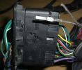
New Speaker Cables.107 viewsThis is the door connector, Main loom to Right, Door side to the left. to the top of the connectors you can see green and Green white wires which are the speaker ones. The door wiring is premium and has two pairs, the main loom was a 1 pair high line, so i am adding the pair you see (one already pinned up) to upgrade the loom to premium.
|
|
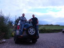
2011 in Fife20 viewsMy old D2 wiyh me on the left and my son Michael on the right. The day before he flew out to Afghan. Returned safe and well six months later.
|
|
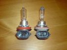
H9 on the left after modification266 views
|
|

Discovery Owners' Club Stand, Gaydon 2005817 viewsScorpio's D3 (on the left) with a LR owned Disco on the DOC's stand at the Gaydon Show 2005
|
|

59 viewsYou can see how the spot to mount the control box has the long flat section to the left - so I mounted the box upside down to allow the 2-sided tape to stick to this bit.
|
|
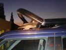
Not the FR rack, but what was left of the Land Rover rack after a door incident213 views
|
|
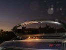
Not the FR rack, but what was left of the Land Rover rack after a door incident173 views
|
|
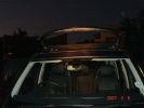
Not the FR rack, but what was left of the Land Rover rack after a door incident148 views
|
|
Not the FR rack, but what was left of the Land Rover rack after a door incident168 views
|
|
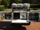
Kitchen open, fridge on right, drawers on left220 views
|
|
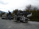
Destroyed D3156 viewsAll that is left of a D3 after plunging down the Verdun Gorge in the South of France.
|
|
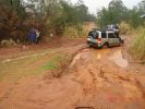
mud recovery216 viewsI think this is atacama in the poo. Heine is out of the picture to the extreme left. Note the white recovery rope stretching out of the frame
|
|

Genral Grabber hardly worn - lots life left18 views
|
|
285 viewsSo guess which idiot left their tow hitch on? No wonder we stopped!
|
|

207 viewsLining up for the last two runs - only one make of vehicle left in the comp!
|
|
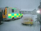
Company car left out in the cold (one on the left) Yellow pearl belongs to her indoors159 views
|
|
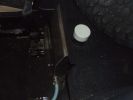
Internal 40 Litre water tank - top view of left side of tank105 viewsShows my spare tyre, but also bright white protective cap of top fill point and vent. Blue hose is water dispensing point. Note seat bracket bolt secures tank to D3. Similar bolt point on other side. Only these two bolts secure the tank and it is very secure.
|
|
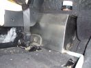
Left hand side of internal 40 Litre water tank161 viewsView from floor looking towards tank. Top white cover is 50mm plastic pipe cap. It protects the tank vent valve. Dispensing hose is at lower corner of tank
|
|
Top view Left side of water tank127 viewsThis view shows the protective cap off, displaying tank vent point.
|
|
Left side (looking forward) of radiator after grill and bumpers removed.101 viewsTape measure is shown for illustration of dimensions only.
|
|
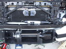
Front bumper view of semi-installed winch118 viewsNote the left-side (looking forward) bracket holding the white windscreen washer bottle.
|
|
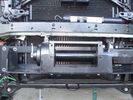
Close-up front view of partially-installed winch120 viewsNote that the sheet-metal flange just above the winch had to be notched to allow winch controller to be actuated. Also this same bracket had to be bent upwards to allow the winch hydraulic:electic solenoid to fit without rubbing. The nut on the upper-left bolt (the one with a very faint circle around it) stripped on re-installation, so the tray and winch pulling load is held only by the threads on 7 bolts....
|
|
310 viewsLeft hand side impact absorber almost touching cooling system on NA spec truck. Absorber required modification.
|
|

399 viewsCloser view of leftside impact absorber. Note the thin piece of plastic I placed between the absorber and the cooling system component. Note air suspension hoses covered by protective tubing at bottom of photo.
|
|
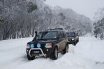
Mt Skene, Victoria, Australia - leading 2 D2s up the hill...192 viewsA great snow season in 2008. The Mt Skene road is one of the few alpine roads that is left accessible, but uncleared, so we can go and play!
|
|
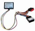
the blackbox to make it play during drive95 viewsplaced on the left side of the radio
|
|
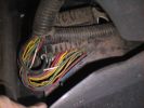
Wiring in left hand rear wheel arch, behind plastic shroud.724 views
|
|
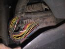
Left hand rear wheel arch, behind plastic shroud.717 viewsThis is the standard wiring.
|
|

213 views
|
|

199 views
|
|

192 views
|
|

181 views
|
|

213 views
|
|

179 views
|
|

193 views
|
|

176 views
|
|
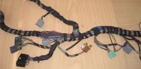
Finished Passenger Kick panel area123 viewsMissing connetor (left most grey) & wiring in, (plastic bracket was broke will use the one in the car) Airbag wires & connector to connector previously cut replaced (on top of grey one to right).
And you can even see the 2 new speaker wires going into the Pass door connector at the very bottom.
|
|

Damaged doorpost left-front/ left-rear20 views
|
|

Missing grip seat front - left22 views
|
|
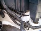
Front Coupler pad to right front under air filter housing 155 viewsThe brighter white "square" behind the black air cleaner drain is the Coupler Pad location I chose for the right front corner. The 1/4", (5mm), black wiring loom carries a single blue colour conductor between the power supply and pad.
A second coupler pad, (white conductor), is located near the left rear tail light. The mounting location is accessible from the rear compartment access "door" where the trailer hitch wiring attaches to the factory loom.
|
|

25 views
|
|

30 views
|
|

Thread upload24 viewsImage uploaded in thread 101157
|
|
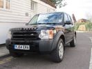
Front left38 views
|
|

Thread upload3 viewsImage uploaded in thread 150295
|
|

70 views
|
|

Thread upload7 viewsImage uploaded in new thread
|
|
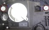
Left Headlight15 viewsLeft Xenon headlight showing adjusters
|
|
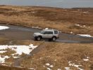
No one about .. Left it running .. just in case ... LRA would take awhile !163 views
|
|

Thread upload4 viewsImage uploaded in thread 160151
|
|

Left side of tailgate carpeted trim piece39 views
|
|
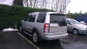
New D4 lights 193 viewsRear left view
|
|
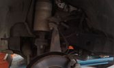
Front left wheelarch71 views
|
|
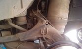
Rear left wheelarch70 views
|
|

Rear left wheelarch61 views
|
|

The on/off switch for the middle outlet8 viewsThe left switch without the label is the one that now controls the middle 12V outlet on the second row. It used to be the power on/off of the car-computer.
|
|
Led location - red led on left A pillar 25 views
|
|
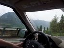
my left arm26 viewsmy wife is great at photos
|
|

Bruin 350 (left) and TRX300 (right)111 viewsMy mates and mine quads! Should have seen the field =]
|
|
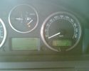
1003.5 km on ONE tankfull, 11L left according to onboard computer124 viewsmore than 1000 km (103.5) done on one tankfull, 11L left according to onboard computer
|
|
Wheel geometry216 viewsThe geometry on the left is the before, anything in red is out of spec, the settings on the right are afte the 4 wheel alignment was finished.
|
|
End of the line at Ras Al Khaimar65 viewsI am led to believe that this example was left overnight on the beach broken down - by morning the natives had stripped every last piece of usefull equipment out of it, engine and all and dragged it across the creek back to their village
|
|
NSF left connection blocks25 views
|
|
NSF left bolt on subframe member27 views
|
|
NSF left subframe part23 views
|
|
Led right hid left fog light 45 views
|
|
Missing bit179 viewsNot sure if I\'m missing a bit on the left, like there is on the right ?
|
|
Existing 3rd row backseat lever (left side from back of car)29 views
|
|
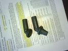
old and new elbows21 viewscomparison of elbows (left is the one that was deteriorated)
|
|
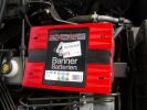
Aux Battery1054 viewsShows the aux 65Ah battery in place, top left of the picture is the 100amp circuit breaker feeding items sutch as , inverter, sub bass amplifiers, computer.
|
|
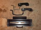
Roof box fixings375 viewsTop original with new one in middle!
Had to make the hole to the left of the plate longer to fit new brackets, it was the same size!
|
|
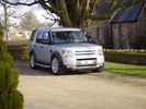
2005 D3 with New Bodykit (from TLO).444 viewsJan 2010
One of the last body kits bagged from TLO in Jan 2010... colour-coordinated in Zambezi Silver by local spray shop... Left the centre section Brunel silver for contrast. Really pleased with the resulting look.
Sadly missed
|
|
98 viewsPlug removed from left hand side of dash to locate wires from clove box
|
|
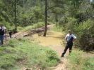
Chief instructor (left) and another instructor explaining water crossings200 viewsWhilst no one tested the waters this time (they did last week with another group) you can just see the stick floating in the water (near second instructor's right elbow). Satisfied that the rains hadn't changed the depth dramatically, they let us through - those that elected to take the water crossing of course.
|
|
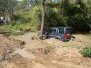
Buckingham Blue goes through260 viewsRutted track to left of shot is where my car went rather than through the water. Mine still is only a few months old - maybe in 6 months or so I will try but at least I know that because other D3s did it on the day, I can when I am game enough!!
|
|

top left hand side fitted66 viewsto show how its angled to fit in with the mouldings
|
|
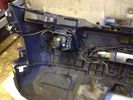
Front left D4 Bumper66 views
|
|
left167 views
|
|
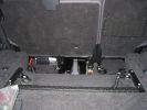
510 viewsMP3-changer and PC beneath the back seats (5 seater). Left and right, 2 USB hubs
|
|
reartire379 viewsRear left tire off the rim! Took 4 guys to get it back in (prefered no to use spare if possible)
|
|
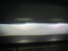
upgrade d2s bulb left 6000k vs philips d2s colormatch 5000k hids4u74 viewsHIDS4U 6000K D2S vs Philips Colormatch D2S bulb
|
|
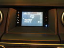
D4 Lowest Grade Radio - Screen Closeup70 viewsThe monochrome screen with colour-lit icons on the left to indicate source, and bluetooth icon on the right to indicate connectivity. There are also two hardware buttons for hour/minute clock setting.
|
|
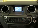
D4 Lowest Grade Radio - Wide Angle75 viewsThe CD player is at the bottom of the picture, the control buttons in the middle, and at the top is the screen with colour-lit icons on the left to indicate source, and bluetooth icon on the right to indicate connectivity. There are also two hardware buttons for hour/minute clock setting.
|
|
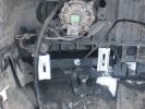
Day Light Driving lights210 viewsFit the lights into the holes cut and then secure. Left hand side.
|
|

sump guard bolts loose 2nd time41 viewsmore bolts left loose by the garage
|
|
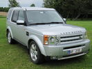
front left37 views
|
|
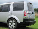
Left side rear38 views
|
|
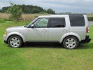
Left side37 views
|
|

front left35 views
|
|
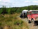
90 left46 viewsvery tight corners in some places
|
|
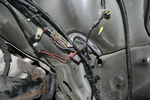
Left inner wheel arch, top128 views
|
|
Left inner wheel arch, front126 views
|
|
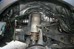
Left inner wheel arch119 views
|
|
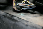
Cross-link valve broken wire105 viewsLeft front inner wheel arch
|
|
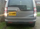
92 LED on right - 21w standard on left - daylight291 views
|
|

Wheels10 viewsA few mm left
|
|

Wheels12 viewsScorpion tyres, a few mm left
|
|
Black Momba227 viewsThis is what's left of a Black Momba in the Limpopo district of South Africa. Note, the inside of their mouth is black, not their bodies. You can see the head resemblance. Check out my friends at African Trophy Pursuit for Hunting, Fishing and Touring the area, they are amazing. https://www.facebook.com/africantrophypursuit
|
|
Rear left Door Arch 16 viewsDamage
|
|
front left Arch 10 viewsDamage to front left Arch
|
|
Left Rear Door arch10 viewsDamaged to the rear left Door arch
|
|
![Filename=IMG_2166 [1024x768].JPG
Filesize=127KB
Dimensions=1024x768
Date added=26.Nov 2007 IMG_2166 [1024x768].JPG](albums/userpics/12685/thumb_IMG_2166%20%5B1024x768%5D.JPG)
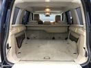
D3 Cargo 1176 viewsCargo fully loaded left
|
|

Img 382 viewsRemove the glove box by pulling on the left
|
|

The reason we bought the DIsco137 viewsMurphy (left) and Boris (right)
|
|
Inflating the boat at Foz176 viewsBruce had 2 Gemini inflatables on top of the Defender, with 2 engines in the rear compartment. Inflating the boats took about 30 minutes. The plan was to cross the Cunene and greet the miners on the Namibian side, which is where the Outside Edge expedition had left off a couple of weeks prior - they couldn\'t cross the Cunene in Land Rovers, so they had to go around - a detour of some 2000km
|
|
EGR replacement27 viewsUndoing the right hand valve is much easier that the left one.....
|
|
EGR replacement16 viewsLeft side - where the hell is it?
|
|
EGR replacement19 viewsThe left EGR valve is tight up against the turbo boost pipe. This make insertion of the long bolts difficult!
|
|
EGR replacement14 viewsBack of left EGR cooler was a swine to replace the clip. Bound it with wire before using pincers to clip together.
|
|
left bank36 views
|
|

121 viewsThe tom tom did say "in 350 yards turn left" ????
|
|
what you should be left with after the blanking procedure8 viewsApart from this, you'll also have to remove the pipes that connect the valves to the airbox. Not mandatory, but a proper job well done
|
|
Butterfly valve and varous leftovers from the EGR valve blanking and pipe removing17 views
|
|

21 views
|
|
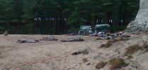
Bodies, note the man on the left has an arrow in his head!57 views
|
|

From left171 views
|
|
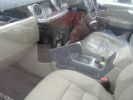
Interior from left180 views
|
|
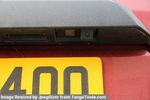
Number plate Camera 68 viewsThe camera includes a number plate light lens - left hand side of the camera.
Just plug in existing number plate bulb
|
|

Thread upload2 viewsImage uploaded in new thread
|
|
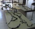
Looms laid out119 viewsview of both a d3 and sport loom from rear left quarter, the single tailgate sport is slightly to the left of the split D3. This was the only real area of difference.
|
|
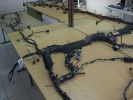
Wiring Laid out shown from other side121 viewsDamaged Disco 3 loom on bottom and new Sport one on top. This angle is as if you were looking at the drivers seat from the front (RHD). You can see the amp wiring centre shot and the rear door wiring to the left all duplicated.
|
|
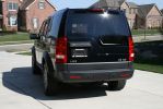
169 views
|
|
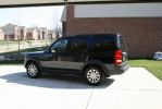
171 views
|
|
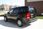
158 views
|
|
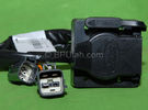
Harness section that runs behind the rear bumper.405 viewsThis is the harness section that clips up inside the rear bumper and includes the circular 7 pin, (6 flat +1 round), NAS socket, and also the 4 pin NAS flat connector.
The two small plug ends connect under the rear left tail light to the harness section that exits from the interior.
The Land Rover part number for the NAS trailer tow kit, (both cables), is YWJ500220.
|
|

Harness that connects inside left rear compartment.435 viewsThis is the harness section that connects behind the left rear interior access panel and exits thru the large grommeted hole to below/behind the left rear tail light.
Note the two rubber grommets on the harness as there is both an interior metal skin and an exterior metal skin behind the left tail light assembly.
The two light grey connectors plug into two existing connectors near the top of the rear left interior access panel. The two darker connectors plug into the second piece of harness.
There is no little separate fuse box either with the NAS spec harness. The fuse box is included with the UK 13 pin dual plug units. If there was a fuse box, it would be on this portion of the harness.
|
|
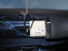
Left Antenna box195 viewsBehind trim left side rear windoa
|
|
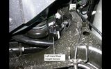
left hand rear height sensor108 views
|
|

24 views
|
|
45 views
|
|

206 views
|
|

Thread upload0 viewsImage uploaded in new thread
|
|
Thread upload1 viewsImage uploaded in thread 197022
|
|
Thread upload9 viewsImage uploaded in new thread
|
|
Thread upload0 viewsImage uploaded in new thread
|
|
Thread upload8 viewsImage uploaded in thread 126537
|
|
Thread upload9 viewsImage uploaded in thread 126537
|
|
Thread upload6 viewsImage uploaded in thread 126537
|
|

Thread upload6 viewsImage uploaded in thread 126537
|
|
Thread upload6 viewsImage uploaded in thread 126537
|
|
Thread upload6 viewsImage uploaded in thread 126537
|
|
Thread upload7 viewsImage uploaded in thread 126537
|
|
Thread upload6 viewsImage uploaded in thread 126537
|
|
Thread upload6 viewsImage uploaded in thread 126537
|
|
Thread upload5 viewsImage uploaded in thread 126537
|
|
Thread upload5 viewsImage uploaded in thread 126537
|
|

Thread upload2 viewsImage uploaded in thread 195046
|
|

Left Overs97 viewsMy donar loom is a bit smaller, and of course there is now a small pile of removed wires.
|
|

Thread upload1 viewsImage uploaded in thread 198799
|
|

24 views
|
|
Thread upload0 viewsImage uploaded in thread 205170
|
|
Thread upload0 viewsImage uploaded in thread 205170
|
|
Thread upload0 viewsImage uploaded in thread 205170
|
|

Left vent with Piano black dash kit fitted568 views
|
|

Left vent with standard grey plastic445 views
|
|
Thread upload13 viewsImage uploaded in thread 99905
|
|
Thread upload4 viewsImage uploaded in new thread
|
|
Thread upload2 viewsImage uploaded in new thread
|
|

Thread upload2 viewsImage uploaded in new thread
|
|

LR Electric Trailer Brake C2590 Female Connector598 viewsThis female connector, C2590, located up above and near the brake pedal is for the Trailer Electric Brake Controller hookup.
The Black wire in the bottom right is pin #3, the ground. The Blue wire to the left is pin #6, the Trailer Brake Controller output going to the rear trailer socket.
The White #4 wire is the 30 amp fusible link, (Link 6E in the engine compartment junction box), for the Brake Controller 12VDC power feed from the battery. Note that this would make a pretty good power source for CB radios and the like if no electric trailer brakes were required.
Pin #5 is a Green wire from the stop lamp switch, (the control input for the Brake Controller).
This plug is standard on all NAS (LR3) vehicles, but unlikely to be found on the D3 spec units.
|
|

Thread upload2 viewsImage uploaded in thread 204346
|
|
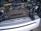
19mm wiring loom in trough behind bumper and in front of rad790 viewsThe 19mm wiring loom is large enough that a maximum of six 6mm air lines can be fished thru as required. The loom runs from the FASKIT panel located in the engine compartment behind the left front headlight, down and across in front of the rad and then down to the front axle valve block located behind and below the right fog light.
|
|
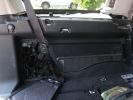
370 viewsHere is the left rear trim panel removed. GTR proved useful in the removal process! The cubby box snaps on to the top of the panel.
|
|
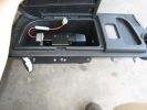
413 viewsHere is the left rear cubby box with the TM-D700A bolted inside. I also drilled a hole in the bottom of the cubby for antenna, GPS, and power wiring, and a hole in the front for control, microphone, data, and audio cabling.
|
|
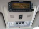
388 viewsCompleted Install of Control Panel. Wiring goes up into headliner, over curtain airbag on left hand side, and down the B pillar.
|
|

LR3 Air Conditioner Drain Tubes behind centre console2091 viewsThis shows the two air conditioner drain tubes located left and right under the radio stack.
The tube on the left side, (steering wheel side, LHD), disattached itself and the carpet on the floor under the gas pedal etc became soaked. I think rain water from outside that comes in the outside cowl vents also exits via the tubes as I first noticed the carpet was wet after parking outside during a big rain storm.
It was relatively easy to slide up and reattach the rubber hose that runs from the rectangular shaped plastic discharge hole(s) of the heater "pan" down along the transmission hump area and thru the floor pan. There is a hose on each side of the transmission hump, but only one hose had let go on my 3. The rubber hoses just slide over the rectangular plastic openings of the two heater housing drain outlets.
To get at each drain hose, remove the vertical sort of triangle carpeted piece below each side of the radio stack. The triangles of carpet will just pull away as each is held on with those metal U clips Land Rover so likes. Dislodge each triangle at least sufficiently to get ones hand in to slide the rubber hose back on.
You will rarely see AC water on the ground as the front drains pour onto a metal underside protection skid plate and the rear drain onto the top of the left rear muffler.
|
|
Battery Maintainer switch box and connector 716 viewsThe Hammond box contains a DPDT toggle switch with centre off. The Positive and Negative from each battery feeds to the switch. Depending on the setting of the toggle, (full left, full right,or centre off),the respective batteries connect into the pigtail that can stick out thru the grill when one wishes to connect the charger.
This allows one to charge each battery independently via a suitable battery maintainer. I use a CTEK unit that feeds a maximum of 3.3 amps at 14.4 or 14.7 VDC, depending upon setting. The wiring therefore allows for a slow recharge of either of the batteries separately if either one requires such.
|
|
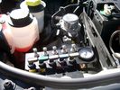
View of mounted panel from front left side872 viewsNote that all valve handles are shown in the OFF position, (the trouble position). In this case, the air that is in the air springs, (if any), is trapped in there - that is the valve blocks cannot vent whatever air is already in the air springs as the air lines between the springs and respective valve blocks are closed off by the FASKIT valves. In operation, there may be only trouble with one air spring, (perhaps a wheel height sensor), and as such, only one valve would need to be closed. If there was complete air compressor failure, then all valves would be closed and then as required, each spring could be manually filled from an outside clean dry oil free air source.
|
|
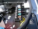
View of mounted panel from front left corner732 viewsI drilled a hole for the supplied 6 mm tie down toggle bolt in a flat portion of the wing on which the panel sits. I inserted a 50 mm flat rubber washer between the wing metal surface and the underside of the black painted panel plate; also a 40 mm flat rubber washer between the supplied fender washer and the metal plate - just seemed like a good idea so surfaces mate well even if wing metal not completely flat.
|
|
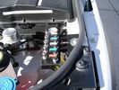
View from front left side looking towards rear aux battery compartment under cover 642 viewsAs there is no Fuel Burning Heater in the NAS V8 petrol vehicles, there is space available to install the FASKIT panel here. The piping is such that each air spring can be isolated from the air system and then filled one at a time manually via the Schrader valve. There are five Schrader valves and five shutoff valves. The fifth valve nearest the gauge controls air from the compressor, and can provide fill up air via a jumper fill line assuming the compressor is still operational.
|
|
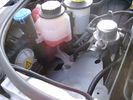
Empty space in NAS LR3 for location of FASKIT panel595 viewsThe empty space is available as the North America Spec gasoline engine LR3's do not have the Fuel Burning Heater installed. The air lines from the four air springs and the air tank will appear to rise up from under the headlight assembly. The lines to the front block valve assembly located behind the front right fog light will sort of run within the bumper across the front of the radiator down into behind the righthand fog light. The rear lines somewhat follow the path of the existing air feed line from the front valve assembly to compressor. Rather than be located between the left front fender liner and left metal wing however, the four lines will feed thru the empty wing space inside and above the wheel well arch and exit down by the left front mud flap. From there, the lines run along the left frame member above the air tank and then parallel the frame over top the compressor to the top of the rear left air spring where the rear air block valve assembly is located.
|
|
Flexible wire rope fishing leader 0.032" diameter exiting carpet 1931 viewsThis is all you see of the completed mod.
The short little angled "line" about an inch long that looks like a piece of debris and is located a few inches "above" the support cable is actually the wire rope release cable exiting from under the carpeted lift gate cover.
I drilled a very small hole in the carpet and pushed the 0.032" diameter release wire thru and then slipped the loose end under the black plastic.
To release with the lift gate etc closed, from the inside, just pull the loose end free from under the black plastic and gently pull wire about 5mm, (1/4"), and the upper door catch should release. You will have to manually push the upper door out wards to actually effect opening, but you will already be inside the rear cargo area so that part is easy to do.
The assumption is that the lower door latch still works electrically and hence, the lower lift gate half will open as normal by pressing the usual button on the top left of the lower door half.
|
|
19 mm wire, (tubing), loom rising from below at left headlight652 viewsFrom the FASKIT panel, five air lines fit in the 3/4" (19mm) wiring loom and feed to the front air valve block located behind and under the right front fog light.
|
|

Wiring (tubing) loom at left headlight showing FASKIT panel 581 viewsThis shows the wiring (tubing) loom and FASKIT panel mounted to left wing. The loom moves a a couple of inches (50mm) towards the bottle once the headlight is put back in as there is not enough free space for the loom as located. The FASKIT panel is just visible at the top left corner of the picture.
|
|
Wiring, (tubing), loom exiting temporarily from the front right fog light.565 viewsThe front axle air valve block is located just behind and below the fog light. Access to the valve block is by removing the right front fender liner, (or the bumper). The FASKIT lines are attached to the left and right front air spring lines at this location; also compressor air is taken from this location as well. Cutting the lines at as few different locations makes it easier to find leaks at a later date. As above, five 6mm air lines run from the FASKIT panel to the front axle air valve assembly and run within the loom. Two pair of the lines are for control of the air springs, and the fifth line taps the air supply at the valve block assembly off the compressor. This will be the air source line rather than tapping in directly to the high pressure air tank.
|
|
Reach Dam-left side342 views
|
|

we put the fuses in the rear panel as well as the air tank gauge, air switch, and battery switch.411 views
|
|
sill up to my knees during extended mode.354 views
|
|

LR3 AJV8 block heater location631 viewsThis 1 page pdf shows the screw in block heater location as related to the lower left side of the engine block.
|
|

LR3 Brake Wear Sensor Wiring1488 viewsThis 1 page wiring diagram pdf shows that both the front and rear brake pad wear sensors are part of a closed series circuit to ground.
In operation, when all is good, the series circuit is grounded and the amber brake wear warning indicator on the instrument panel is not illuminated.
When the pads on one wheel, either the left front, or right rear, become too worn, the respective sensor is "cut" which results in an open circuit condition. This causes the dash brake wear indicator to illuminate.
The circuit is like the old style Christmas light strings where one burned out bulb caused the whole string to go out.
A quick field fix to get the dash light to extinguish in lieu of replacing the sensor and pads etc is to disconnect the brake pad wear sensor and short across the two open conductors of the vehicle side connector plug. This of course means you now have a normal vehicle, one of the thousands that do not feature brake pad wear information systems.
|
|
LR3_front_left_bias22 views
|
|
![Filename=LR3_Radio_Removal[1].pdf
Filesize=190KB
Dimensions=320x240
Date added=04.Feb 2014 LR3_Radio_Removal[1].pdf](images/thumb_pdf.jpg)
Radio Removal from Radio Stack567 viewsThis shows how to remove the radio from the stack. Basically you remove the H surround first and then at least loosen all the Torx 20 screws left and right sides from the top down starting at the narrow unit that the four way flasher/locking buttons are mounted on.
The units kind of interlock, hence some movement of each is required to remove the radio by itself. I find it best to take out the four way flasher/locking buttons assembly first as that allows access to the fibre optic cable connector into the back of the radio head without too much tugging.
|
|

Compare LR lettering101 viewsWhat happens when you let the dealer 'fix' the problem of deterioration of the bonnet badge lettering. Compare the left with the right side (LAND cf. ROVER). Only one side was 'fixed' under warranty.
|
|
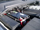
Main starting battery showing 1/2" hole drilled for power cable egress905 viewsView of OEM battery in Left Hand Drive LR3. This is supposed to be a Battery Group BCI 49 or H8 sized battery but in reality is the slightly shorter BCI 94R or H7 battery that fits easier lengthwise, (12 3/8" vs 14").
Note the 10mm hole drilled in plastic of surround to allow for entry of main power cable that runs between batteries. The cable bolts to a spare 6mm threaded hole in the OEM battery cable end; the light gauge wire runs to the front of vehicle to a connector for the CTEK MULTI US 3300 charger. Coloured felts, (red and green), are a material treated to reduce battery post corrosion. The OEM battery ground cable is only about a foot long and runs to an 8mm stud located on the inner fender just to the rear of the fuse case.
|
|
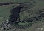
176 viewsShows the Monsal Head pub bottom left, and on the far the track we went up at the top right
|
|
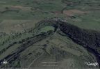
Google Earth image of Monsal Dale174 viewsShows the Monsal Head pub on the far side and the track we came up at the bottom slightly to the left
|
|
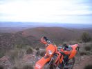
KTM on Stokes Hill106 viewsLeft the Disco somewhere safe
|
|
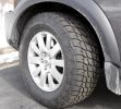
Right after install292 viewsHere is the left front Terra Grappler right after install. My they\'re big!
|
|
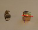
3 viewsI modified a compression fitting collet (right) to match a Landrover voss fitting collet (left) by cutting at the lines as shown. Intended as a temporary fix for a leaking voss fitting, but has worked great for several years.
|
|
traxide ground 666 viewsTraxide Install - Left hand drive Ground Strap in place.
|
|
Traxide699 viewsLeft hand drive, primary battery with Traxide cable routed. The battery is on the right.
|
|
Left hand trim1000 viewsLeft hand trim
|
|
Left hand trim769 viewsLeft hand trim
|
|
Left hand trim733 viewsLeft hand trim
|
|
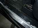
Left hand trim991 viewsLeft hand trim
|
|
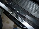
Left hand trim1041 viewsLeft hand trim
|
|
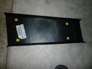
Left hand trim1049 viewsLeft hand trim
|
|
firewall plug run835 viewsThrough the firewall to the right of the brake master cylinder. On left hand drive, this hole would be closest to the outside edge of vehicle.
|
|
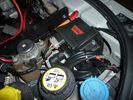
warn winch controller installation607 viewsremotely installed due to space limitations, and to keep the unit dry. Left Hand Drive, fitted in engine bay near washer fluid fill for reference point.
|
|
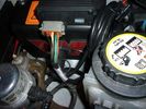
warn winch controller installation541 viewsremotely installed due to space limitations, and to keep the unit dry. Left Hand Drive, fitted in engine bay near washer fluid fill for reference point.
|
|
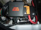
warn winch controller installation566 viewsLeft Hand Drive, fitted in engine bay near washer fluid fill for reference point.Remote control unit fitted on the box. Remotely installed due to space limitations, and to keep the unit dry.
https://www.facebook.com/DifferentialPartsUS
|
|
rear socket install1386 viewsTraxide rear socket installation, alternative location. These holes must be precisely in this location because there is little clearance to the right of left due to the blower motor and hoses, etc.
|
|
Negative Battery Cable203 viewsThis shows the corrosion from the negative terminal on the Negative to body ground. This is likely due to gas released through the negative post. It appears to be a common problem with the LR3. As a result of this corrosion left unchecked will damage the computer ecu and cables mounted near and below the battery.
|
|
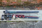
Maxxraxx35 viewsMaxxraxx fixed towball mounted bike rack. Top: upright with pivot and locking pin. Bottom left: towball mount with spacer and 50mm towball. Bottom right: horizontal member with three bike carriers, securing strap and security cable.
|
|
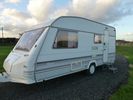
Left Side.103 views
|
|
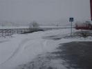
snow storm result77 viewsleft about 40cm snow
right 0cm snow
|
|

We draw the left board45 views
|
|

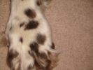
Front left paw63 views
|
|
Front left paw59 views
|
|
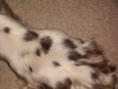
Front left paw60 viewsLump on his front left paw. About 2+ years old. Identified on x-ray with fluffy edge
|
|
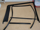
Rear Left hand side door seals24 views
|
|
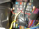
Fuse Panel showing F35P Add A Circuit installed1230 viewsFive amp fuse F35P is located towards the top left in this jpg. The other three Add A Circuit devices are for other items - powering my cell phone base etc.
Note the orientation of the Add A Circuit as this matters. Also one can just see a red tab sticking out from behind the device. The red is the conductor crimp end of a narrow 2.8mm male spade type connector that inserts into one of the "fuse" slots.
|
|

Yamaha Bruin 350 (left), Honda TRX300 (right)104 viewsMy mates Yamaha Bruin 350 on the left and my Honda TRX300 on the right
|
|
216 viewsThe inner workings of the floor console. You can see the inline fuse holder on the left, which then connects to the chill box connector.
|
|
122 viewsThats Me (mine) on the left at McDonalds Kempsy New South Wales. (Next to two older siblings)
|
|
Rear coupler pad located near rear left tail light 144 viewsThe rear coupler pad is not visible as it is located "below and behind", so to speak. Follow the loop of black plastic wire loom from right to left as the loop of loom covering the white conductor wire drops down "behind" to the flat metal surface the pad is glued to. The pad is attached to the flat metal surface via a 3M sticky on the backside of the coupler pad.
|
|

17 views
|
|

Rear quarter panel removal171 viewsThe left hand side has the PDC module amongst others in it.
The one for the bluetooth module is the drivers side pannel.
|
|
Thread upload9 viewsImage uploaded in new thread
|
|
Thread upload5 viewsImage uploaded in thread 150295
|
|
Thread upload4 viewsImage uploaded in new thread
|
|

Redundant Parts972 viewsThese are what you are left with once the EGR blanking kit is installed. Best to hang onto them in case you need them again!
|
|
Bolts to remove left bracket of FBH with exhaust pipe22 views
|
|
Reservoir Bung 24mm socket 1149 viewsThis is the view of the air tank at the end nearest the front left wheel. This is what you see before you do the mod. The other view is after the mod.
On pre 2008 models, there is this 24mm socket hex head bung, M20 x 1.5 thread, that can be unscrewed and the Schrader valve assembly installed instead. On newer 3's the bung hole was deleted from the front end of the air tank; hence the mod as described, is then not possible.
|
|

56 views
|
|
Hi Line stereo plugs with radio removed. Aux plug on the left14 views
|
|
175 views
|
|
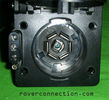
NAS 7 pin + NAS 4 pin Flat Trailer Socket304 viewsThis is the vehicle end of the NAS trailer harness that is located behind the removable plate centered within the rear bumper by the towing loop. Re the four pin flat connector, from the bottom, the exposed bare lower pin is the ground, usually the White wire on a NAS trailer. The next pin up is normally a Brown wire on a trailer and is for the Tail Lights. The third pin, normally a Yellow wire, is the left signal light; the top pin, normally a Green coloured wire, is the right signal light.
Re the round connector, from the notch in the plastic surround, clockwise, the first blade is ignition controlled +12VDC battery power, (only alive when engine running), and on the Land Rover factory harness is an Orange wire; on a NAS trailer, usually Red but perhaps a Black wire.
Next blade clockwise at 3:00 o'clock above, is the Right Turn signal light, a Green wire on the LR harness, and also on a NAS trailer.
At 5:00 o'clock, the next blade is for the Electric Brakes and is Blue on both the LR harness and on a NAS trailer.
The Ground wire is next, White on both the LR harness and on a trailer.
At 9:00 o'clock above, is the Left Turn signal, Yellow on both the LR harness and on a trailer.
The last blade to the left of the line up notch is the Tail Light circuit. On the LR harness, the wire colour is Brown with two White stripes and on a NAS trailer, Brown.
The centre pin is for the Reverse Back Up lights and is Black on the LR harness and often Purple on NAS trailer wiring but can be Black also.
Note that when the socket assembly is installed on the 3, the notch in the plastic surround is on the left - that is rotated 90 degrees anticlockwise to the picture above. In other words, When installed on the 3, the 4 pin flat connector lays horizontal and is located below the round socket.
|
|
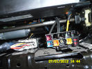
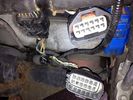
96 viewsConnectors under my driver seat..
Right connector for Heated seat + airbag ++
Left connector for Seat controll I hink
|
|
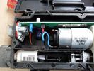
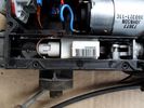
The lid is off!425 viewsShows motor, circuit board and left cable inner end
|
|
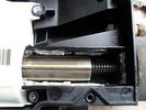
Now we are getting to it...439 views... the threaded (or DREADED) actuator - externally splined internally threaded element (centre of pic) rotated by gearbox (on left of pic) to pull cable end (externally threaded, on the right)
|
|
Strain gauge...391 views...I think.
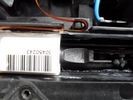
On the left cable - with a latch (?function) and a ribbon connector cable
|
|
Release cable...361 views...passes round the pulley on the left...
|
|
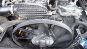
47 viewsYou will need to hold the fan drive in place whilst you undo the large nut in oder to remove the fan. This is a Left Hand thread, so it undoes by turning in a Clockwise direction.
|
|
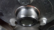
38 viewsThis is a Left Hand thread, so it undoes by turning in a Clockwise direction.
|
|
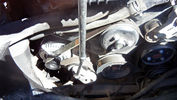
64 viewsThis is easy to remove. You will notice the tensioner at the bottom left near the alternator. There is a sqaure slot on the tensioner into which fits a 3/8" square drive. Just turn anti-clockwise and the tensioner is moved away to slacken the belt and off it comes.
|
|
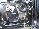
Left hand bass speaker35 views
|
|
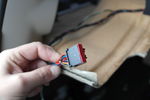
Roof connector41 viewsConnector located left side in the roof of the boot near the D pilar Left hand side
|
|
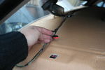
Roof connector Front41 viewsConnector left hand side in roof
|
|
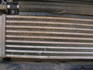
Blocked intercooler left side107 views
|
|

Frozen Satnav48 viewsThe left hand screen continues to update, as does the text in the detail view, but the map in the detail view is frozen at the first of the series of junctions - location circled in the main view
|
|

Thread upload2 viewsImage uploaded in thread 193123
|
|

My old Seadoo RXT 290 viewsOn holiday with the ski's, St Tropez France.
My RXT on the left, supercharged & intercooled 1500cc rotax engine...aftermarket freeflow intake system by RIVA, SOLAS blueprinted prop, race sponsons, RIVA intake grate & opas system removed for less drag...estimated 230hp.
Proven 70mph (with GPS & Radar gun)
On the right is my best man's GTX Ltd. with 185hp and good for 60mph with a tail wind...
|
|

slave prices31 viewsthe left side is the age and sex the right side the value.
|
|

36 viewsLeft the dog out last night!
|
|
42 views
|
|
4x4 channel video switch (low) + alpine 425i on top left134 viewsmy car is 5 seater, so there is room under the seats...
|
|

Two complete sets of Rear Tail Lights11 views2 X Left Hand Rear Lights and 2 X Right Rear Lights
|
|

Tekonsha Ford Brake Controller Adapter part number 3035-P270 viewsThis is the adapter cable between the Brake Controller and the existing C2590 female plug located near the brake pedal on NAS spec LR3's. The flat 4 pin plug of the adapter cable connects to the Controller; the rectangular 6 hole male plug to C2590.
There are only four conductors in the adapter cable, but one will see five pins within the Land Rover C2590 plug. The #2 pin is not required for the NAS setup. #2 pin is the circuit between the head lamp switch and vehicle side running lamps required in the civilized world.
The single pin at the bottom in the picture is #3 and on the Land Rover, a Black wire tied to ground. The other pin at the bottom and across to the left is #6, and Blue on the Land Rover. This is the Brake Controller output to the trailer socket at the rear.
#4 is the pin at the top left, and is a White coloured wire from the battery. Pin #5 is from the stop light switch, and is Green on the Land Rover.
Note that the adapter cable colours do not necessarily follow all the above referenced Land Rover colours.
|
|
![Filename=thumb_DSCN1852[1].jpg
Filesize=3KB
Dimensions=133x100
Date added=20.Apr 2014 thumb_DSCN1852[1].jpg](albums/userpics/33463/thumb_thumb_DSCN1852%5B1%5D.jpg)
rear audio in 31 viewsleft the D3 audio input socket
right freelander 2 video audio input module
|
|
Thread upload6 viewsImage uploaded in new thread
|
|
Thread upload7 viewsImage uploaded in new thread
|
|
Thread upload5 viewsImage uploaded in new thread
|
|
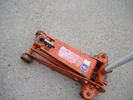
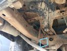
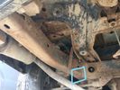
Trolley Jack Adapter817 viewsThis shows my 2.5 long ton, (2,540 kg, 5,600 pounds), trolley jack with the pin adapter that slots up into the round holes on the underside of the frame.
Use of the adapter when lifting by the left rear wheel ensures that I will not be jacking on the air compressor support; on the other three corners, it is much safer than merely jacking directly on the nearly flat narrow underside of the frame rail.
|
|
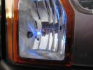
left hand blue led177 views
|
|
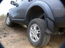
Wheel travel262 viewsStopped the car to check wheel travel; front left on small mound, rears both on ground - unbelievable!
|
|

Modified Wiring diagram for the added electrical bits25 viewsI made this wiring diagram during the cleanup I did lately.
I completely removed some 'old' electrical bits I had installed and used the occasion to document every left and new part.
|
|
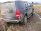
Wheelspining at left rear wheel stopped me 8-))157 views
|
|
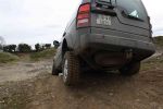
plough on96 views
|
|
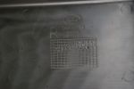
Stamp in base of right (as in drivers, RHD, left when viewed from front of engine bay) cover108 views
|
|
|
|
|
|