| Search results - "pressure" |

Thread upload12 viewsImage uploaded in thread 159335
|
|
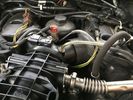
Boost pressure sensor conn.2 views
|
|

Thread upload1 viewsImage uploaded in thread 126959
|
|
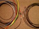
6mm PA12 grade nylon tubing with heat shrink applied 538 viewsShows some of the 6mm air line with heat shrink applied to one end of tubing. Shrink will be applied to the other end once field cut to length. These four tubes, each about 20 ft (6m) long, feed to the rear. Re the front air lines, (not shown), four additional lengths, each about 10 ft (3m) long, are required plus one more 3 metre length for compressor air. The 6mm tubing is a Nylon product specified as PA12. There is also a very similar Transport grade PA11 material, however it seems that PA12 is the more common Transport grade now in use. Also the applicable DIN standard seems to be both DIN 73378 and DIN 74324 for the nylon tubing. The working pressure of the 6mm tubing is about 27 Bar and bursting 82 Bar @ 20C. This is for the 1mm nominal wall thickness material, (4mm ID, 6mm OD).
|
|
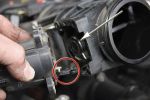
Removing the EGR Butterfly Valve Actuator1521 viewsRemove the 4 TORX screws to remove the actuator. The small black link (circled) connects the actuator drive arm with the butterfly valve spindle (arrowed). The spindle can now be very carefully levered out using a screwdriver inserted beneath the arrowed bit in the photo. A bit scary to do as it takes a fair bit of pressure before the spindle will free itself from the butterfly. Once it starts moving though, it gets easier to pull out.
|
|

291 views
|
|
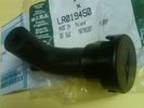
Breather Cap part # LR0194501509 viewsThis is the replacement breather cap as manufactured by the Gore Tex people, (Gore), for the engine compartment end of the front differential breather line.
You can with some difficulty, both blow and suck thru the breather filter material. The Gore Tex filter material has what are called hydrophobic and oleophobic properties. This means the filter material keeps oil in and water out, while at the same time, allowing air pressure to slowly equalize, (air permeable). Additionally, the transfer of dust, salt, and road debris is inhibited.
|
|

MAP sensor29 views
|
|

Gallery Pressure16 views
|
|

Gallery Pressure21 views
|
|

Manifold absolute pressure sensor30 viewsCleaning the map sensor
|
|

32 views
|
|

D4_oil_pressure_table16 views
|
|

79 views
|
|

Suggested Tyre Pressures75 viewsTyre pressures used onroad and offroad, using both OEM HT and Goodyear MTR tyres.
|
|

Oil Pressure Specs65 views
|
|
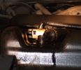
Damaged area65 viewsPic shows plastic breather fitting with the corner ground away. When tank reached full fuel is pushed out under forecourt pump pressure. The second occurrence shows similar damage.
|
|
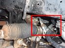
Detail of hydraulic hoses attached to power steering hoses153 viewsHoses are attached to the upstream side of power steering rack. When winch not running, PS rack sees full pressure (ie, no change from design). Biggest challenge is running stiff hoses so that they align with attach points. I got Qantas employee who repairs hydraulic baggage loaders to braise in fittings (very tight spaces and tough access).
|
|
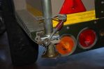
fitted stronger rear strut holders. not a great mod. the holes i drillled for the "R" clips are the best mod, as they stop the legs from sliding up under pressure. requires bracing inside to stop chassis bending100 views
|
|

Wynns EGR3 Spray Instructions88 views
|
|
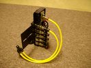
FASKIT on end view 859 viewsEnd and rear view of the FASKIT. Yellow lines are as shipped for hooking to the air supply; one line to valve/filler and other is to gauge. I will modify the arrangement to delete one of the yellow lines such that gauge line plugs into where the second yellow line is right now,(will be only one yellow tube), and then the air source line will plug into the port controlled by the valve, (hidden in this view but visible in other view). When white valve is in the ON position, gauge will read air source pressure, and be available to supply air to any of the selected four air springs. When valve is closed, the gauge will show individual air pressure in each of the air springs when a jumper is run between the gauge Schrader valve and the appropriate air spring Schrader valve.
|
|
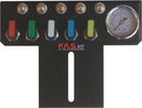
FASKIT air panel unmounted836 viewsThis is the manual air valve panel that is mounted in the "empty" space where the FBH normally resides. The gauge reads to a maximum of 25 Bar. The air tank relief valve is set just over 16.5 Bar (240 psig); the front air springs run maybe 9 Bar, (130 psig) and the rear, somewhat less, perhaps between 5 and 8 Bar. (70 to 115 psig). Max theoretical air spring pressure at full compression due to a big bump and full gross is approximately 27 Bar (390 psig).
|
|

Thread upload1 viewsImage uploaded in thread 181247
|
|
Thread upload13 viewsImage uploaded in thread 163344
|
|

Thread upload2 viewsImage uploaded in thread 198300
|
|
Thread upload6 viewsImage uploaded in new thread
|
|
Thread upload6 viewsImage uploaded in new thread
|
|
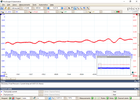
Thread upload6 viewsImage uploaded in thread 141122
|
|
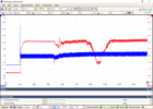
Thread upload6 viewsImage uploaded in thread 141122
|
|

Thread upload1 viewsImage uploaded in new thread
|
|

Thread upload1 viewsImage uploaded in new thread
|
|

Gore Tex data sheet on Breather Cap.769 viewsThis is a Gore data sheet on the air vent material that is within the breather cap. The filter material has both hydrophobic and oleophobic properties. That means it keeps water out and the differential oil in.
Also the membrane material is air permeable; that means air pressure is equalized between the interior of the differential and outside air. This is important when the 3 is flying at altitude in the back of a Hercules with the rear door open - that is the rear hatch of the Herc.
|
|

Gore Tex Oleophobic Membrane Vents70 viewsThese is a link to a Gore website that explains how the Gore Tex material within the breather cap allow pressure to escape (but retains the oil) and allows moisture free air to come back in but excludes free water.
|
|

137 views
|
|

47 viewsFuel Pump recall
|
|
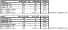
EAS Suspension Pressures By Gap17 views
|
|

D4 Oil Level and Fuel Pressure12 views
|
|
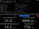
D4 Fuel Pressure15 views
|
|

D4 LP Fuel Pressure and Amps14 views
|
|

Pressure transducer 119 views
|
|

Pressure transducer 325 views
|
|

Pressure transducer 227 views
|
|

LP scoped 218 viewsBy connecting a Low Amps probe to the fuel pump's voltage supply wire, you can view the pump's current waveform on a digital storage oscilloscope (DSO). The scope pattern will reveal internal wear in the brushes and commutator that may not show up in a traditional pressure or volume test.
Observing the waveform will show if the pump's amp draw is normal for the application or is high or low, and if the pump is operating at normal speed or is running slow. Problems such as a bad spot on a commutator or a short or open in the armature also will be obvious in the waveform.
A "good" electric fuel pump waveform will generally seesaw back and forth with relative consistency and minimal variation between the highs and lows. A "bad" waveform will show large or irregular drops in the pattern, with large differences between the highs and lows.
|
|

Gallery Pressure Before Start21 views
|
|
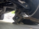
off road height, jack in position, no pressure, just touching547 views
|
|

Showing compressor, tank, pressure switch564 views
|
|
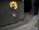
On switch and pressure guage551 views
|
|
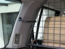
Paddock dog guard - counter-lever263 viewsThese fittings provide the counter-lever thus securing the guard in place (against the pressure from the J-bolts)
|
|

Fuel pressure at startup1 viewsFuel pressure starts at about 0.3 bar when ignition is on and lift pump is priming - then it goes off the scale - engine starts but it is not as smooth as normal
|
|
pressure test49 views
|
|

Thread upload6 viewsImage uploaded in thread 187038
|
|
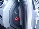
Air Suspension ECU Fuse 35P cut off switch.3802 viewsThis shows the SPST rocker switch mounted in the blank plate installed in lieu of a manual passenger side air bag shut down switch - now automatic via passenger seat pressure switch. Fuse 35P (5 amps) is located in the interior fuse box behind the lower glove box and protects the ignition power supply to the Air Suspension ECU. When the SPST switch is moved to the OFF position, the RAISE /LOWER switch on the centre console is not powered, and hence does not function. As such, some signals from the wheel height sensors and CPU are ignored. By itself however, removing F35P will probably not stop the 3 from self dropping, particularly after the engine is turned off.
Fuse F3E, (5 amps), located in the engine bay fuse box by the starting battery protects the circuit that provides feedback to the Air System ECU indicating that the Compressor Relay has successfully operated and that the Air Compressor is or should be operational, can also be removed, (but is probably not totally necessary), as it gets its power thru F26E. Hence Fuse F26E, (20 amp), also located in the engine compartment fuse box is the fuse that must be removed. This fuse protects the circuit that provides full time battery power to the Air System ECU. When in place, current thru the fuse powers the periodic re-levelling action, (usually lowering a bit with that brief air release noise), that often occurs when the vehicle is parked and the engine is off.
Removing F26E fuse will stop the auto levelling action and also inhibit any other down to the stops signals, (engine running or not). When F26E is removed, no power can flow thru to F3E, hence removing F3E is more for insurance than an absolute requirement. The same with F35P, removing F26E removes primary full time power from the Air Suspension ECU, and hence removing the F35P fuse should not really be required either as long as F26E has been removed.
|
|

Wheel cut thru definitions and specs894 viewsNote the location of REAR SPACING and also OFFSET; probably two of the most important dimensions and not always understood as related to wheel size and relationship to the brake components.
For the 3, Rear Spacing is approximately 6.5 inches or 165 mm for a nominal 8" rim. Offset is 53P or 53mm Positive, which means the distance from the machined hub flat mounting surface to the rim's true centreline is 53 mm in the outboard direction. (The rim illustrated has a negative offset.)
As Positive offset increases, this means the wheel wraps around the disc brake mechanism more deeply, and hence the more the wheel would cover the brake parts. This is why most 18" wheels will not fit with the larger Brembo "supercharged engine" brake calipers.
Pitch circle diameter is 120mm; Pattern is 5 lug, and the tyre load rating is 112 with a recommended tyre speed rating of H or higher along with the XL load rating. For the 3, the stock tyre diameter is about 30 inches. The 255/60/18 or 255/55/19 OEM tyre outside diameter is 30.04 inches; Wheel lug torque is from 130 to 150 Nm or 96 to 110 lbf-ft and the lug nut hex socket size is 22mm.
Max Load High Speed Driving Tyre pressures are Front, 33 psig, (230 Kpa) and Rear, 42 psig, (290 Kpa).
The OEM rims are rated at 940 kgs, the highest that LR makes, hence while rims from other Land Rover products may physically fit, the odds are they are under rated in a weight sense.
|
|
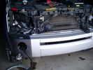
Wiring, (tubing), loom exiting temporarily from the front right fog light.565 viewsThe front axle air valve block is located just behind and below the fog light. Access to the valve block is by removing the right front fender liner, (or the bumper). The FASKIT lines are attached to the left and right front air spring lines at this location; also compressor air is taken from this location as well. Cutting the lines at as few different locations makes it easier to find leaks at a later date. As above, five 6mm air lines run from the FASKIT panel to the front axle air valve assembly and run within the loom. Two pair of the lines are for control of the air springs, and the fifth line taps the air supply at the valve block assembly off the compressor. This will be the air source line rather than tapping in directly to the high pressure air tank.
|
|

LTB00109 - Technical Bulletin - Cooling System Pressure Test64 views
|
|

LTB00221 - Technical Bulletin - Tire Valve Stem Damage During Manual Tire Pressure Checking57 views
|
|

Thread upload4 viewsImage uploaded in thread 198463
|
|
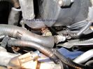
Pressure hose from psp53 views
|
|

Fuel pressure at startup1 viewsFuel pressure starts at about 0.3 bar when ignition is on and lift pump is priming - then it goes off the scale - engine starts but it is not as smooth as normal
|
|

Thread upload5 viewsImage uploaded in thread 151737
|
|
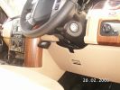
236 viewsVehicle Unit Display held on with Velcro, easily removable
|
|
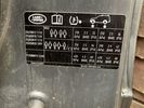
Thread upload2 viewsImage uploaded in thread 200286
|
|
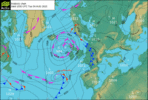
Thread upload9 viewsImage uploaded in thread 132903
|
|
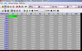
Thread upload24 viewsImage uploaded in thread 133088
|
|
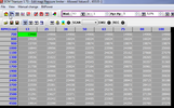
Thread upload30 viewsImage uploaded in thread 133088
|
|
Thread upload41 viewsImage uploaded in thread 133088
|
|

Thread upload22 viewsImage uploaded in thread 133088
|
|

Thread upload37 viewsImage uploaded in thread 133088
|
|

Thread upload27 viewsImage uploaded in thread 159240
|
|

161 views
|
|
Thread upload2 viewsImage uploaded in thread 199252
|
|
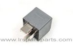
Air Compressor 70 amp replacement relay1384 viewsThere is a software update, 09 April 2010, LTB00270, for the compressor which reduces the shut down pressure to about 205 psig (14 bar). The update is usually done when changing to a new compressor and also includes replacing the R7 relay in the engine compartment fuse box, 07 DEC 2010 LTB00331.
The newer grey case coloured relay, part # YWB500220, shows to be rated at 70 amps, (the relay, not the compressor), however the previous black case coloured relay also indicates 70 amps.
Both the new and replaced relay show on their wiring diagrams to have a parallel voltage spike resistor, (probably 560 ohms), across the coil terminals, #1 and #2. This means one does not just replace the relay with any four prong 70 amp ISO sized relay that one happens upon.
One presumes the grey relay is either upgraded or just being installed for good measure. The relay is common on Ford Fiesta for the seat heater relay, Ford part number 5M5T 14B 192 EA; also Volvo, part number 30765034. The Tyco part number moulded on the grey body is V23136-J4-X62.
|
|
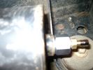
Reservoir Air In fitting installed 1648 viewsSchrader valve installed. Shop air can now be introduced into the tank to facilitate the raising of the 3 when there has just been a failure of the onboard air compressor rather than the electronics or valve block wiring etc.
Air could also be sourced from this point, however the purpose of the modification is air in, not air out as the air pressure normally runs above 200 psig, too high to be safe for routine use unless a pressure reducing regulator is added per the Mitchell Bros kit.
|
|

Thread upload9 viewsImage uploaded in thread 154448
|
|

Thread upload12 viewsImage uploaded in thread 154448
|
|
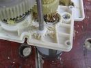
Gear box casing showing wear from screaming friction...407 views...once the circlip has bust through the inadequate retaining land, the spring presses on the (other) gearbox casing, forcing the secondary gear to wear on the gear box casing where shown, there being no adequate provision for end-thrust (even though helical gearing would mandate that, to cope with the NORMAL axial vector forces produced) resulting from spring pressure on the other gearbox casing face pushing the gear into this face.
|
|
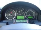
ScanGauge II on steering column of LR3797 viewsMAP is Manifold Absolute Pressure, what I call Vacuum.
The volts is I think the battery charging voltage as it moves around from about 12.4 when shut down to 13.5 when the batteries seems charged; 14.9 is about as high as I have seen it display.
You also have RPM, speed in MPH or KPH, coolant temperature and a bunch of other readings including sort of instantaneous fuel in a variety of units.
Also under some conditions, the ScanGauge will reset the MIL light as well. The background colour of the display can be changed to many different colours. I have it set to match the LR green.
|
|

Thread upload0 viewsImage uploaded in thread 133933
|
|
150 views
|
|
![Filename=Technical Service Bulletin SB034 SB036 Vehicle Enhancement Program[1].pdf
Filesize=959KB
Dimensions=0x0
Date added=17.Jun 2010 Technical Service Bulletin SB034 SB036 Vehicle Enhancement Program[1].pdf](images/thumb_pdf.jpg)
Technical Service Bulletin SB034 SB036 Vehicle Enhancement Program2383 viewsOn page 6 and following are the Land Rover service bulletin instructions as to how to install delivery valve and exhaust valve repair kit JPO500010; also a list of previous compressor model numbers as related to the 3. The new delivery valve is easy to install, the exhaust, not so easy. Note that this in not the more recent TSB that reduced the operating pressure of the compressor via a software fix and also recommended replacement of the air compressor 70 amp relay. See the F35 album near the bottom for the relay material.
|
|
32 views
|
|

Tyre pressure monitoring valve21 views
|
|
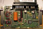
transfer case control module71 viewsPicture shows blown components of the Transfer Case control module after water ingress over time - with a healthy top up from over-enthusiastic lad with a high pressure water hose in the car wash!!!
|
|

Thread upload24 viewsImage uploaded in thread 133088
|
|

Thread upload29 viewsImage uploaded in thread 133088
|
|

Thread upload35 viewsImage uploaded in thread 133088
|
|

Thread upload20 viewsImage uploaded in thread 133088
|
|

Thread upload34 viewsImage uploaded in thread 133088
|
|
Thread upload14 viewsImage uploaded in new thread
|
|

Thread upload13 viewsImage uploaded in new thread
|
|
Thread upload2 viewsImage uploaded in thread 199186
|
|
Thread upload7 viewsImage uploaded in thread 141122
|
|
|
|