| Search results - "socket" |
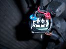
Chinese socket power outlet16 views
|
|
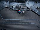
Chinese socket location13 views
|
|
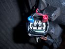
Chinese socket14 views
|
|
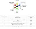
Thread upload5 viewsImage uploaded in thread 176361
|
|

13 Pin Socket Towing Electrics Fitting Instructions222 views
|
|

Thread upload2 viewsImage uploaded in thread 171152
|
|
Thread upload10 viewsImage uploaded in thread 184914
|
|

Thread upload2 viewsImage uploaded in thread 198799
|
|
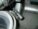
The 3.5mm socket for ipod etc.3584 views
|
|
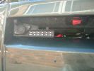
Socket for control lead and switch for radio-remote moved from solenoid pack to bumper1030 views
|
|
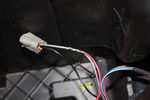
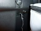
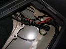
108 viewsThis is the plug for the accessory socket at the rear of the cubby box. On commercial D3 such as this one, there is no accessory socket so this plug is unused. I tapped into the 12V wire as an ignition feed. This will feed a relay coil which opens up power from the aux battery. Like this I can still retro fit and make use of the accessory socket later on.
|
|
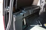
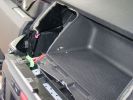
78 viewsHole for 12V accessory socket. This hole has a blanking plate on it on Commercial D3s. It just needed to be filed down in some areas to fit the socket I bought.
|
|
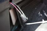
72 viewsWiring for 12V socket attached to socket
|
|
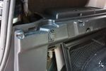
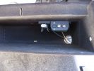
91 views12V socket done. This is permanently powered by the Aux battery. Another one was done on the other side, though that one required drilling the hole with a 29mm hole saw as there wasn't an unused hole on that side.
|
|
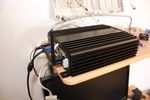
79 viewsCarPC closed and ready for mounting. Note the modification to the rear of the case to allow extra USB sockets attached to the motherboard pins.
|
|

78 viewsExtra USB sockets mounted to front of commercial box, just behind cubby box
|
|

63 viewsCut a slot in the socket grip to fit the cutout
|
|
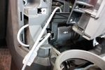
62 viewsCutout done, all that's left is to stuff the socket into the cutout
|
|
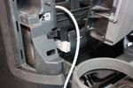
69 viewsUSB socket finally wedged in place. Cable routing will take the same route as VGA screen cables
|
|
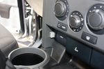
86 viewsAll back in place. Front USB socket final result.
|
|

51 views
|
|
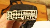
Sockets to be improved77 views
|
|
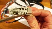
Removing a socket45 views
|
|
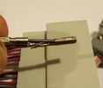
Connector sockets 8-12 & 21-2340 views
|
|

Twin 7 Pin Socket Towing Electrics Fitting Instructions260 views
|
|

Tow Electrics69 views
|
|

Add A Circuit Littelfuse Data sheet2264 viewsThe switch connects to what Littelfuse brand calls an Add-A-Circuit model FMH200BP which is an adapter that plugs in place of a Mini fuse and then has space for two Mini fuses, (original and a second one). In this install, only the original 5 amp fuse was used - adapter was so as to route power from fuse box thru fuse, then rocker switch, and then back to fuse box.
Before you install the Add A Circuit for this application, take an ohm meter and trace out the circuit path of the four slots that fuses could insert into. The path is more complicated than one might first think. As such, the orientation of the fuse holder in the socket matters for this application - that is for a circuit diverter, rather than accessory adder.
|
|
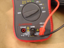
Amprobe 240 Test Sockets29 views
|
|
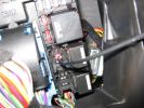
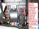
aux sockets relay - remove the relay and put in link wire 189 views
|
|
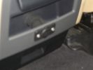
Auxiliary power sockets - TracTronics, Australia381 viewsA complete kit including two outlets, wiring etc connected to auxiliary Optima Blue top battery using their very effective SC40 split charge relay. One outlet between rear and front seats, and 2nd alongside loadspace 12v outlet, enables fridge to run when engine is not running, without affecting start capacity or vehicle functions.
|
|
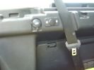
TracTronics loadspace power socket 379 viewsThe 2nd power socket fitted alongside the original in the loadspace runs off the auxiliary Optima Bluetop battery to run a fridge when engine is not running. No more starting worries!
|
|
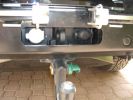
LR towing electrics pack 12N/12S312 viewsThe LR trailer electrics fitted before the Kaymar bumper and spare wheel carriers required no modifications are perfectly accessible. Good strong recovery point between the sockets too. The swing awau wheel carrier securing latches can be seen quite clearly here. Long Ranger tank (painted black) nestles where orignal spare was fitted.
|
|

Mounted in 12v socket from driver\'s side42 views
|
|
Thread upload4 viewsImage uploaded in new thread
|
|
LHS Headlight Plug Socket21 views
|
|

inverter and 12v socket262 views
|
|
Thread upload16 viewsImage uploaded in thread 123573
|
|
Thread upload17 viewsImage uploaded in thread 123573
|
|
Thread upload16 viewsImage uploaded in thread 123573
|
|

Cover with 2 12V sockets, 2 USB sockets and 220V socket18 views
|
|
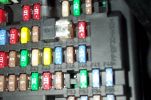
Tapa-Circuit Fuse Tap407 viewsTapa-circuit fuse tap fitted in existing fuseway provides extra fuseway which I have used to hard wire my Tomtom Sat Nav PDA. The fused output feeds into a female socket (Cigar lighter sized) into which the tomtom power adaptor is plugged. All hidden away behind the glove box.
|
|
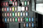
Tapa-circuit Fuse Tap431 viewsTapa-circuit fuse tap fitted in existing fuseway provides extra fuseway which I have used to hard wire my Tomtom Sat Nav PDA. The fused output feeds into a female socket (Cigar lighter sized) into which the tomtom power adaptor is plugged. All hidden away behind the glove box.
|
|
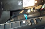
Hard wired tomtom493 viewsThe fused output from a tapa-circuit feeds into a female socket (Cigar lighter sized) into which the tomtom power adaptor is plugged. All hidden away behind the glove box.
|
|
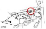
Diagnostic socket location105 views
|
|
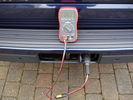
Volts via Tow Socket 358 views
|
|
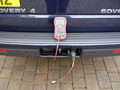
Volts via Tow Socket 263 views
|
|
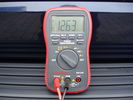
Volts via Tow Socket 144 views
|
|

Additional 12V power, battery monitoring and USB sockets104 views
|
|
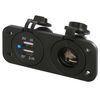
Thread upload2 viewsImage uploaded in new thread
|
|
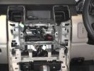
Everything out \'cept the sockets at the bottom \'cos they\'re a bitch580 views
|
|
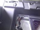
12volt socket in place and access hatch to get the input lead564 viewslook for the purple and black input lead
|
|

Edited Headlight socket14 views
|
|
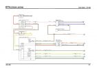
357 views
|
|
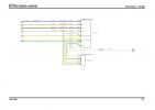
363 views
|
|
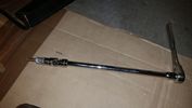
Thread upload17 viewsThis is how you reach that TOP BOLT holding your air compressor bracket on. 10" extension, swivel, and 10mm socket taped so it won't fall off while your feeding it through the air compressor maze.
|
|
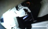
Socket found attached inside the grille - behind the LR badge51 viewsThe socket was attached behind the grille - and connected but to what I do not know
|
|
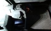
Wires under the bonnet 142 viewsLooking inside the grille - centre. No socket here.
|
|
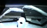
Wires under the bonnet 141 viewsLooking inside the grille - centre. No socket here.
|
|

Searching for the correct Aux socket in passenger footwell176 views
|
|

Thread upload2 viewsImage uploaded in new thread
|
|

Thread upload4 viewsImage uploaded in new thread
|
|

Thread upload2 viewsImage uploaded in thread 187340
|
|

H9 lamp socket4 viewsWired directly thru HL Connector
|
|
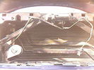
Front Horn and extra cable and socket234 views
|
|
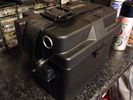
33Ah leisure battery in ABS case with Fused 12v socket44 views
|
|

New impact sockets22 views
|
|

Ceiling Sockets 133 views
|
|

Ceiling Sockets 232 views
|
|

FT-8900 radio body mount95 viewsYaesu FT-8900 mounted on access door. Multi-way socket on front.
|
|
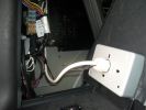
220v Socket889 viewsPicture showing the back of the Inverters 220v socket
|
|
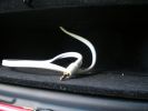
101 viewsstandard 3.5mm headphone plug/socket extension
|
|
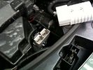
Where the socket is86 views
|
|
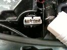
Socket in place97 views
|
|

PP002 12V128 views Brad Harris Socket
Hella Socket Cigarette
Lighter Socket
Battery Level Meter
External Terminals for Battery Charger or Solar Panel
ON/OFF isolator tie down strap excludes Battery
Built in fuses
https://www.facebook.com/snomasterusa
|
|

Power sockets23 viewsI moved the two power sockets over from D3 to D4, both with ebony interior. One Merritt socket for fridge, and another standard socket for recharging devices.
|
|
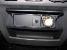
12v Socket in centre console331 views
|
|

EPB elec socket30 views
|
|

7mm Socket to open connector box22 views
|
|

7mm Socket to open connector box26 views
|
|

39 viewsRear, switched, always live dual USB charging socket
|
|

Towing socket battery charging cable38 views
|
|
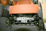
Passenger Seat fitted, 8 way movement via power sockets408 views
|
|
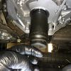
Used a large impact socket to tap the seal in place10 views
|
|
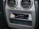
311 views
|
|
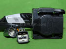
Harness section that runs behind the rear bumper.405 viewsThis is the harness section that clips up inside the rear bumper and includes the circular 7 pin, (6 flat +1 round), NAS socket, and also the 4 pin NAS flat connector.
The two small plug ends connect under the rear left tail light to the harness section that exits from the interior.
The Land Rover part number for the NAS trailer tow kit, (both cables), is YWJ500220.
|
|

Lidl_Socket_Set58 views
|
|
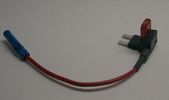
Littelfuse Mini Add-A-Circuit FMH200BP and OFH0200ZP1610 viewsFound this jpg somewhere on the forum - others are using them as it is a good way to tap the fuse box to add a fused circuit, or in this case, to modify a circuit to add a switch such that the fused circuit is switched. In my SmoothTalker gallery, there is a PDF from Littelfuse specifically related to this Add-A-Circuit device.
Before you install the Add A Circuit for any application, take an ohm meter and trace out the circuit path of the two pair of slots that fuses could insert into. The path is more complicated than one might first think. As such, the orientation of the fuse holder in the socket may matter depending upon the application. If the application is a circuit diverter, (as the F35 mode is), as opposed to a mere accessory adder, orientation matters.
|
|

LR Electric Trailer Brake C2590 Female Connector598 viewsThis female connector, C2590, located up above and near the brake pedal is for the Trailer Electric Brake Controller hookup.
The Black wire in the bottom right is pin #3, the ground. The Blue wire to the left is pin #6, the Trailer Brake Controller output going to the rear trailer socket.
The White #4 wire is the 30 amp fusible link, (Link 6E in the engine compartment junction box), for the Brake Controller 12VDC power feed from the battery. Note that this would make a pretty good power source for CB radios and the like if no electric trailer brakes were required.
Pin #5 is a Green wire from the stop lamp switch, (the control input for the Brake Controller).
This plug is standard on all NAS (LR3) vehicles, but unlikely to be found on the D3 spec units.
|
|

NAS 7 Blade Round plus NAS 4 Pin Flat Vehicle end Socket522 viewsThis shows the function of each blade when looking into the connector at the vehicle end for the 7 pin NAS plug. The layout is the pin order for most new North American pickup trucks and the LR3/4.
The colour and gauge of the wires feeding into the back of the plug varies even within manufacturer model lines.
Also detailed is the flat 4 pin layout common on smaller trailers not having electric brakes. This includes most U-Haul rental trailers.
|
|

NAS 7 Pin Round Socket + 4 Pin Flat Socket oriented as installed.742 viewsThis is the layout you see when you look into the NAS Land Rover sockets as installed at the rear of the LR3/4. The flat 4 pin socket is located under the round socket.
Wiring order is relative to the slot on the round socket, and hence the same as the other jpg where the slot is shown at the top.
The CJB monitors the front and rear turn signal lamps and can detect if more than four lamps are fitted, (the side turn signal lamps are not monitored). This is another reason for using genuine LR bulbs as off shore bulbs can have varied and out of spec resistance values.
When a trailer is detected, the trailer warning indicator in the instrument cluster is supposed to flash green in synchronization with the turn signal indicators.
If one or more of the turn signal lamps on the vehicle or the trailer are defective, the trailer warning indicator will cease to flash any longer. This is to alert the driver to probably bulb failure.
If the trailer has LED lamps installed, and no LED adapter circuitry is used, most likely the trailer will not be sensed and systems such as the backup sensors will not be disabled.
|
|

Wheel cut thru definitions and specs894 viewsNote the location of REAR SPACING and also OFFSET; probably two of the most important dimensions and not always understood as related to wheel size and relationship to the brake components.
For the 3, Rear Spacing is approximately 6.5 inches or 165 mm for a nominal 8" rim. Offset is 53P or 53mm Positive, which means the distance from the machined hub flat mounting surface to the rim's true centreline is 53 mm in the outboard direction. (The rim illustrated has a negative offset.)
As Positive offset increases, this means the wheel wraps around the disc brake mechanism more deeply, and hence the more the wheel would cover the brake parts. This is why most 18" wheels will not fit with the larger Brembo "supercharged engine" brake calipers.
Pitch circle diameter is 120mm; Pattern is 5 lug, and the tyre load rating is 112 with a recommended tyre speed rating of H or higher along with the XL load rating. For the 3, the stock tyre diameter is about 30 inches. The 255/60/18 or 255/55/19 OEM tyre outside diameter is 30.04 inches; Wheel lug torque is from 130 to 150 Nm or 96 to 110 lbf-ft and the lug nut hex socket size is 22mm.
Max Load High Speed Driving Tyre pressures are Front, 33 psig, (230 Kpa) and Rear, 42 psig, (290 Kpa).
The OEM rims are rated at 940 kgs, the highest that LR makes, hence while rims from other Land Rover products may physically fit, the odds are they are under rated in a weight sense.
|
|
a few items being built in behind cover panel.435 viewsred inverter will have fluch mount plugs, air outloet will be flush, guage with window in lower pop-panel and switches and fuses for all rear items behind popout panel.
12v sockets being added as well, high and low.
|
|

Thread upload37 viewsImage uploaded in thread 47507
|
|
Thread upload40 viewsImage uploaded in thread 47507
|
|

Lug Nut part number RRD500290 outline sketch538 viewsThis single sheet pdf provides dimensions of the LR part number RRD500290 lug nut on vehicles from MY 2005 to 2008, (up to VIN 8A450459). From VIN 8A450460, the part number is RRD500590.
Visually, there is no apparent difference between the two part numbers. The dimensions appear identical as well. The shape, size, and profile of the Stainless Steel "hat" appears identical.
There are I presume differences in metallurgy to reduce corrosion and swelling of the hat or perhaps better sealing between the inside surface of the hat and the steel of the lug nut body. The reality is the differences are not immediately obvious however.
A 22 mm six point half inch or larger socket drive fits over the lug nuts. I use a nominal 36" long breaker bar with the 22mm socket - any shorter bar, best you be in shape. Depending upon your source, for both alloy and steel wheels, the lug nut torque value appears to be 103 lbf ft, (140 Nm); others suggest first tighten to 96 and then finish at 110 lbf ft, (130 and 150 Nm).
|
|

AUX power in rear of Disco101 viewsUsing hella aux power socket & cool magcode power port, also from hella,
|
|
Pass-through sockets51 views
|
|

NAS 7 plus 4 pin LR3 Trailer wiring, trailer end. 490 viewsThis is the LR wiring diagram showing the conductors from the the Trailer Brake Controller connector, C2590, back to the rear combo NAS 7 plus 4 pin sockets.
|
|
46 views
|
|
94 views
|
|

53 views
|
|
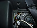
rear socket install1387 viewsTraxide rear socket installation, alternative location. These holes must be precisely in this location because there is little clearance to the right of left due to the blower motor and hoses, etc.
|
|
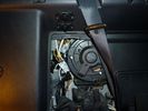
rear socket install1021 viewsShows to white cable run, cable routing, cable ties and socket placement. Rear sockets fitted. Note the white power cable, and cable tie location. The socket in this position are neatly back out of the way, but handy.
|
|
rear socket install825 viewsThis photo shows the rear sockets installed, shows how the sockets in use are tucked up nicely and out of the way.
|
|
rear socket installation complete635 viewsThis demonstrates the rear sockets installed, shows how the sockets in use are tucked up nicely and out of the way.
|
|
rear socket installation complete671 viewsdemonstrate a neat and roomy install
|
|
radar detector wires tucked up high424 viewsThe orange ties hold wiring sockets for floodlights (to be installed). Red tie holds excess wire for radar detector.
|
|
wires tied up tight539 viewsThe Orange ties hold wiring sockets for floodlights (to be installed). Red tie holds excess wire for radar detector.
|
|
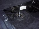
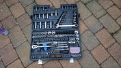
Socket set82 views
|
|
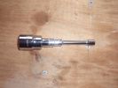
Assembled socket set66 views
|
|
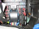
permenant aux sockets ..place link wire here 154 views
|
|
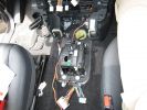
286 viewsPicture of the floor console removed. The wiring moving along from the bottom of the picture forward is power from the rear power socket, and audio from the aux port.
|
|
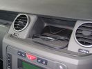
431 views
|
|

91 views
|
|

87 views
|
|

52 views
|
|

Thread upload5 viewsImage uploaded in thread 80646
|
|
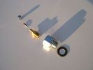
Reservoir Air In fittings exploded view 1885 viewsThis shows the fittings required for the mod. The reducer adaptor requires a 27mm socket and is M20 x 1.5 male thread x 1/4" NPT female. The 1/4" male NPT Schrader valve has the standard valve core removed and an AN/MIL spec aircraft oleo strut valve installed instead.
A standard automobile valve is rated at 200 psig, (14 bar); the air tank runs closer to 244 psig, (16.8 bar), with the relief valve set to open between 334 psig, (23 bar) and 370 psig (25.5 bar). The aircraft valve is rated at 2,000 psig, (138 bar).
|
|
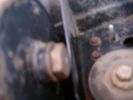
Reservoir Bung 24mm socket 1149 viewsThis is the view of the air tank at the end nearest the front left wheel. This is what you see before you do the mod. The other view is after the mod.
On pre 2008 models, there is this 24mm socket hex head bung, M20 x 1.5 thread, that can be unscrewed and the Schrader valve assembly installed instead. On newer 3's the bung hole was deleted from the front end of the air tank; hence the mod as described, is then not possible.
|
|
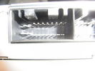
20 pin socket on rear of Hi Line stereo14 views
|
|
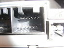
12 pin Aux socket on rear of Hi Line Stereo11 views
|
|
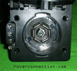
NAS 7 pin + NAS 4 pin Flat Trailer Socket304 viewsThis is the vehicle end of the NAS trailer harness that is located behind the removable plate centered within the rear bumper by the towing loop. Re the four pin flat connector, from the bottom, the exposed bare lower pin is the ground, usually the White wire on a NAS trailer. The next pin up is normally a Brown wire on a trailer and is for the Tail Lights. The third pin, normally a Yellow wire, is the left signal light; the top pin, normally a Green coloured wire, is the right signal light.
Re the round connector, from the notch in the plastic surround, clockwise, the first blade is ignition controlled +12VDC battery power, (only alive when engine running), and on the Land Rover factory harness is an Orange wire; on a NAS trailer, usually Red but perhaps a Black wire.
Next blade clockwise at 3:00 o'clock above, is the Right Turn signal light, a Green wire on the LR harness, and also on a NAS trailer.
At 5:00 o'clock, the next blade is for the Electric Brakes and is Blue on both the LR harness and on a NAS trailer.
The Ground wire is next, White on both the LR harness and on a trailer.
At 9:00 o'clock above, is the Left Turn signal, Yellow on both the LR harness and on a trailer.
The last blade to the left of the line up notch is the Tail Light circuit. On the LR harness, the wire colour is Brown with two White stripes and on a NAS trailer, Brown.
The centre pin is for the Reverse Back Up lights and is Black on the LR harness and often Purple on NAS trailer wiring but can be Black also.
Note that when the socket assembly is installed on the 3, the notch in the plastic surround is on the left - that is rotated 90 degrees anticlockwise to the picture above. In other words, When installed on the 3, the 4 pin flat connector lays horizontal and is located below the round socket.
|
|
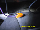
12v connector50 viewsThis one's for Socket Accessory
|
|
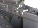
2 new rear 12v outlets933 viewsI added these two after market 12v oulets that are directly wired via a 30amp fuse to the aux battery. Why 2? Well you can never have enuff in my experieince... There\'s also a 12v socket wired to the ignition on the other side.
|
|
12v outlet wires859 viewsonside the drivers side rear hatch, whos the wires joined up for the rear sockets.
|
|
334 views
|
|
1334 views
|
|
Thread upload3 viewsImage uploaded in new thread
|
|

Thread upload2 viewsImage uploaded in new thread
|
|
209 views
|
|
366 views
|
|

Thread upload4 viewsImage uploaded in new thread
|
|
Thread upload9 viewsImage uploaded in new thread
|
|

Thread upload1 viewsImage uploaded in new thread
|
|

Thread upload1 viewsImage uploaded in new thread
|
|

Thread upload1 viewsImage uploaded in new thread
|
|
Thread upload11 viewsImage uploaded in thread 47890
|
|
Thread upload10 viewsImage uploaded in thread 47890
|
|
Thread upload11 viewsImage uploaded in thread 47890
|
|
Thread upload3 viewsImage uploaded in thread 47890
|
|

26 views
|
|
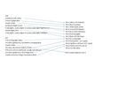
13 pin to 7 pin trailer socket wiring165 views
|
|
![Filename=sx113-32mm-low-profile-oil-filter-socket-fits-tdv6-oil-filter-housing-1311289-filte-1230753-p[ekm]261x270[ekm].jpg
Filesize=9KB
Dimensions=261x270
Date added=17.Sep 2018 sx113-32mm-low-profile-oil-filter-socket-fits-tdv6-oil-filter-housing-1311289-filte-1230753-p[ekm]261x270[ekm].jpg](albums/userpics/33392/thumb_sx113-32mm-low-profile-oil-filter-socket-fits-tdv6-oil-filter-housing-1311289-filte-1230753-p%5Bekm%5D261x270%5Bekm%5D.jpg)
Thread upload6 viewsImage uploaded in new thread
|
|

Tekonsha Ford Brake Controller Adapter part number 3035-P270 viewsThis is the adapter cable between the Brake Controller and the existing C2590 female plug located near the brake pedal on NAS spec LR3's. The flat 4 pin plug of the adapter cable connects to the Controller; the rectangular 6 hole male plug to C2590.
There are only four conductors in the adapter cable, but one will see five pins within the Land Rover C2590 plug. The #2 pin is not required for the NAS setup. #2 pin is the circuit between the head lamp switch and vehicle side running lamps required in the civilized world.
The single pin at the bottom in the picture is #3 and on the Land Rover, a Black wire tied to ground. The other pin at the bottom and across to the left is #6, and Blue on the Land Rover. This is the Brake Controller output to the trailer socket at the rear.
#4 is the pin at the top left, and is a White coloured wire from the battery. Pin #5 is from the stop light switch, and is Green on the Land Rover.
Note that the adapter cable colours do not necessarily follow all the above referenced Land Rover colours.
|
|

Tekonsha P3 Brake Controller 90195 to Ford 3035-P wiring adapter plug306 viewsThis two page pdf is the general instruction for hooking up the Tekonsha part number 3035-P adapter cable between a Tekonsha P3 controller and the existing Land Rover/Ford plug, (called C2590 in the Land Rover wiring diagrams), that is hidden above the brake pedal.
The "Ford" plug, (C2590), is grey and is stuffed up above the brake pedal arm.
Mount the P3 controller appropriately and then connect one end of the custom cable to the P3 and the other to the "hidden" plug.
You will now have power for your trailer electric brakes in the round socket at the rear of your LR3; also no computer update from the Land Rover T4 unit is required. For once, it is plug and play.
If however, your trailer has LED tail lights, you may have trouble with the flashing of the trailer signal lights or non recognition by the 3 that a trailer is connected. As such, the little green trailer signal will not illuminate when a trailer is connected and the signal lights are used. This can affect the shifting of the transmission and much to your annoyance, the backup sensors will still be functioning rather than being auto disabled.
|
|
![Filename=thumb_DSCN1852[1].jpg
Filesize=3KB
Dimensions=133x100
Date added=20.Apr 2014 thumb_DSCN1852[1].jpg](albums/userpics/33463/thumb_thumb_DSCN1852%5B1%5D.jpg)
rear audio in 31 viewsleft the D3 audio input socket
right freelander 2 video audio input module
|
|
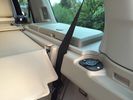
Extra 12V socket18 views
|
|

Thread upload4 viewsImage uploaded in thread 186884
|
|

19 views
|
|
Thread upload0 viewsImage uploaded in new thread
|
|
841 views
|
|
Thread upload12 viewsImage uploaded in thread 173882
|
|

Thread upload13 viewsImage uploaded in thread 184954
|
|
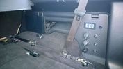
PS2 + Split charge system 10 viewsPS2 - Wireless controllers and headphones.
Split charge system with auxiliary sockets with digital voltage display
|
|
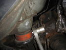
Not enough space for a socket!71 viewshttp://www.disco3.co.uk/gallery/albums/edit/preview_3e2413bb.JPG
|
|

Power socket262 views
|
|
|
|