| Search results - "tea" |
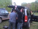
Ken and Slimer tried to steal parts whilst no one was looking!189 views
|
|
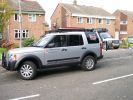
Both Team Poteen vehicles128 views
|
|
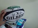
12 viewsGot it signed by the SA team ;-)
|
|

Ready to winch a friends disco 4 194 viewsback of the picture you can just see another freinds (luvbus) disco 3 acting as balast to stop the disco 4 pulling me down hill
|
|
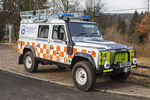
Northumberland National Park Mountain Rescue Team Land Rover Defender 11021 views
|
|
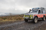
The Northumberland National Park Mountain Rescue Team Land Rover9 views
|
|
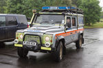
Northumberland National Park Mountain Rescue Team Vehicle10 views
|
|
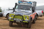
Northumberland National Park Mountain Rescue Team Land Rover15 views
|
|
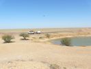
Morning tea - between Diamantina NP and Bedourie QLD19 views
|
|
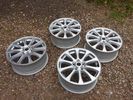
203 views
|
|

95 views
|
|
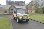
The Northumberland National Park Mountain Rescue Team Land Rover10 viewsDelta Defender
|
|
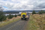
The Northumberland National Park Mountain Rescue Team11 viewsDelta Defender
|
|

The Northumberland National Park Mountain Rescue Team11 viewsDelta Defender
|
|
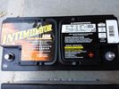
Deka 9A49 AGM Intimidator318 viewsThe Deka 9A49 AGM Intimidator makes an excellent primary battery alternative to the factory or Interstate. Made in US of premium quality. This is an excellent match with the Traxide system w/another Deka or Yellow Top optima.
This will behave properly in your D3/4 LR3 with slightly less wear and tear on your alternator.
|
|

Thread upload7 viewsImage uploaded in new thread
|
|

Thread upload1 viewsImage uploaded in new thread
|
|

The rest of the team!64 views
|
|

Alternator and Regulator Wiring Diagrams, TDV6 and petrol V8 and V61973 viewsThis is a three page pdf that shows the alternator and regulator wiring for the petrol V6, petrol V8 and TDV6. The pdf can be either printed or by right clicking on the displayed pdf, rotated as required for viewing.
Of interest is that the regulator gets its instructions primarily from the Engine Control Module (ECM) and only secondarily from the vehicles electrical buss. The conductor from the battery thru the 5 amp fuse F20E is to provide initial power to excite the alternator at startup and then secondarily, to instruct it if the PWM signals were not available. Primary instructions to and from the ECM are thru the two other conductors via a digital like Pulse Width Modulated (PWM) signal.
If F20E, the 5 amp engine compartment fuse box fuse is blown, the red alternator light on the dash will be illuminated. This means that the alternator could be OK, but if the F20E fuse is blown, no electricity will be generated. Hence check the F20E fuse if you get a red ALT light or some indication of the alternator not working.
Regarding operation of the red ALT light on the dash, it is not the regulator within the alternator that tells the red light to illuminate, or not, but instead the ECM. This is the reason the red light does not function in the same manner as with older vehicles. With the 3, sometimes you have illumination and sometimes not depending upon what the ECM is thinking. What this means is that you can have an alternator that is failing but the red light does not illuminate as the ECM is compensating for reduced alternator output - maybe by draining the battery and or cutting back on vehicle electrical loads such as shutting off or cycling the radio amplifier or heated seats.
|
|

72 views
|
|

Thread upload2 viewsImage uploaded in thread 180038
|
|
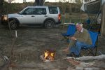
A couple of juicy steaks and a nice red...228 views
|
|

Fin cell phone aerial drawing190 viewsThe factory aerial for the factory NAV / GPS on my 2005 HSE is within the high mounted stop light lens at the top of the upper hatch door. I do not have the factory installed phone kit, and as such, do not have the fin installed; instead there is just a plastic blanking insert to fill the cell phone aerial wiring hole in the metal portion of the roof; hence this requirement for an "external" cell antenna. For those that do have the fin on their glass roof, the fin is screwed on to a glued on plastic gasket, (sort of), and not bolted thru as per the metal roof 3's.
|
|
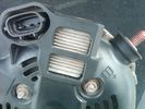
Alternator Plug and B+ terminal910 viewsPictured is the rear of the older Land Rover part # YLE500190 alternator showing the shiny cooling fin of the Regitar VRH2005-142 regulator under.
The first pin in the far left side of the connector is numbered #1 in the LR electrical wiring diagrams and is Battery Voltage Sensing (BVS); the middle pin, #2 receives a Pulse Width Modulated (PWM) signal from the Engine Control Module (ECM), and the right pin, #3 carries a PWM signal back to the ECM. Terminal Pin #2 on the LR wiring diagrams is called Alternator Control or ALT CON; Pin #3 per LR is called Alternator Monitoring or ALT MON.
Pin #1 is similar to what in older designs used to be called A or Batt, but is now called by Denso, S, AS, or Alternator Sensing for this design. Pin #1 also provides power to excite the alternator at startup until the PWM instructions over ride the battery voltage info. Land Rover calls the electronics under the pins a Smart Regulator, ironic, as it has to follow orders from the ECM rather than give the orders - new age thinking I guess. This is different from older design internal regulators that look at just the battery or the electrical buss voltage and then decides itself what to do.
It is almost like we are back to the external regulator designs of old, except that the ECM may decide that instead of telling the alternator to make more power, to load shed, and hence shut down the heated windscreen, seats, or whatever other electrical loads it decides are appropriate. My view is that the "smarts" are in the ECM and that the "regulator" should be regarded if not dumb, then as being a slave to the ECM.
|
|
127 views
|
|
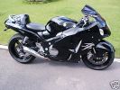
STEALTH BUSA75 views
|
|
Thread upload5 viewsImage uploaded in new thread
|
|

Thread upload2 viewsImage uploaded in thread 159579
|
|

72 viewsThe Smaller Nashers in their SIB which is inflated with an Electric pump mounted in the RIB. Great as a Taxi to and from the beach and for them (and me) to tear about in.
|
|

Brake Light Switch, Find, Remove, and Install Instructions 7775 viewsThis is a two page doc outlining where to find the brake light switch, how to remove it, and then install the new one.
Note, do not move the brake pedal when removing or installing the switch. Let the brake pedal hang where it wants to. The switch design is actually cunning, and as such is supposed to make the removal and install fool proof. Hence if you think too much about it, you can wreck the new switch.
If you want to inspect the interior of the switch, wait until you have removed the old switch. You can then just unsnap the blue from the white to get it apart. Inside, the switch is quite simple, (no circuit boards), but it will probably show black dust from failing contacts.
I think the reason the switch fails is that the Normally Open, (NO), contacts of the brake light contacts were made too light to carry the current load for make and break of the tail light filaments. I also think the black dust created then fouls the Normally Closed, (NC), second set of contacts for the ABS circuit. As such, the Normally Closed contacts become intermittent in operation and display as a fluctuating open and closed circuit condition to the ABS system when the ABS should be seeing a steady closed circuit. Hopefully the replacement switch contacts are more robust and may be as I recently replaced my switch again just as a matter of maintenance. While in a redesign, ideally the NC contacts should be sealed or at least separated from the NO contacts, when I inspected the removed switch, this time there was no black dust present.
Probably the removed switch will have a Land Rover oval logo moulded into it, the new one, FOMOCO.
|
|

camel stearing wheel103 views
|
|

STEADY!!!122 views
|
|
Thread upload20 viewsImage uploaded in thread 135028
|
|
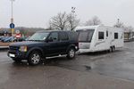
d3andvan151 views
|
|
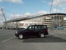
A bare looking Disco 3 at Eastlands back in February 2006163 views
|
|

Propshaft Support - Front view42 viewsNote the quality Sikaflex instead of the pathetic fragile rubber. :-)
|
|
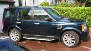
Lugano Teal707 views
|
|

ronaldo transcends tight vest79 viewsThe brazilian football team have requested a new outfit after complaints about tight vests
|
|

115 views
|
|
107 views
|
|
108 views
|
|
109 views
|
|
sticker160 views
|
|

101 views
|
|

104 views
|
|

105 views
|
|
107 views
|
|

108 views
|
|

106 views
|
|
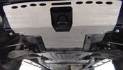
GOE Bash Plates117 viewsGreen Oval Experience Bash Plates. Front, Transmission and Compressor.
Might have to mod the front one a bit to let air into the trans cooler, it sits over the outside of the ARB bar which has vents for the cooler. If I cut slots in the Allow Plate to match those might do the trick.
I added a rear bolt to the Compressor Plate as it looked like it could get hooked on something and tear off. Two bolts onto the slider and two up onto the chassis now.
|
|

Liguana Teal326 views
|
|

Kingsley with Sr. Pedro, the chief of police at Foz Do Cunene, Angola.167 viewsSr. Pedro was initially a bit wary of us, but once King had explained his mission, Sr. Pedro and his team couldn't do enough to help. He even brought us sinkers to fish with and beer when we ran out! Kinsley took him to meet his neighbours from Namibia
|
|
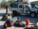
Babu - great guy from Mozambique who joined Kingsley\'s core team.150 views"How the heck am I gonna fit all that in there?!"
Packing all the kit in Ondangwa. Amazing what you can get into a Defender!
|
|
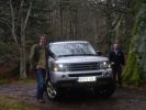
Disco 3 not available, so had to tolerate this awful £60k RRS instead :-o235 viewsOnly the half-day introduction course, but Geordie was an excellent tutor and we had an amazing time.
|
|

Mrs Snowy and the Extreme team on their way roung Boughrood111 views
|
|

calendar entry 2009540 viewsCrossing a river in Iceland June 2008 - some of the rivers have deep sticky black basalt sand on their edges and some times needs a running approach! Car is G4 Challenge Event Car from 2006 - Team Germany / Spain - Stage 3/4 Bolivia
|
|
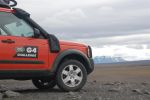
calendar entry 2009528 viewsHigh in the Iceland Interior June 2008 - F88 to Askjar Volcanoe - The mountain is called the "Queen of the Mountains - Herðubreið" Car is G4 Challenge Event Car from 2006 - Team Germany / Spain - Stage 3/4 Bolivia
|
|
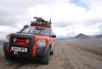
calendar entry 2009582 viewsHigh in the Iceland Interior June 2008 - Car is G4 Challenge Event Car from 2006 - Team Germany / Spain - Stage 3/4 Bolivia
|
|
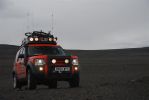
calendar entry 2009542 viewsHigh on the Iceland Interior - On the Road to Askja - G4 D3 Discovery V8 HSE - Team vehicle from 2006 G4 Stage 3/4 Bolivia -
|
|

calendar entry 2009525 viewsCrossing a river in Iceland June 2008 - some of the rivers have deep sticky black basalt sand on their edges and some times needs a running approach! Car is G4 Challenge Event Car from 2006 - Team Germany / Spain - Stage 3/4 Bolivia
|
|
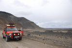
calendar entry 2009540 viewsRoad F88 to Askja - Iceland Interior June 2008 - Car is a G4 challenge event car from 2006 - Stage 3/4 Bolivia - Team Germany / Spain
|
|

calendar entry 2009521 viewsCrossing a river in Iceland June 2008 - some of the rivers have deep sticky black basalt sand on their edges and some times needs a running approach! Car is G4 Challenge Event Car from 2006 - Team Germany / Spain - Stage 3/4 Bolivia
|
|
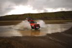
calendar entry 2009539 viewsCrossing a river in Iceland June 2008 - some of the rivers have deep sticky black basalt sand on their edges and some times needs a running approach! Car is G4 Challenge Event Car from 2006 - Team Germany / Spain - Stage 3/4 Bolivia
|
|

calendar entry480 viewsHigh in the Iceland Interior June 2008 - View towards the Vatnajökull Glacier range - Car is G4 Challenge Event Car from 2006 - Team Germany / Spain - Stage 3/4 Bolivia
|
|
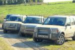
Team 391 views
|
|
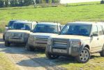
Team 394 views
|
|

Team 393 views
|
|

Team 391 views
|
|

Team 3 Calendar Entry96 views
|
|
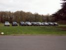
View from the Fairmile Carpark of 9 members cars194 viewsRange Rover Au Poivre had turned up by now - VA was having seat as well as steak sauce problems! I think we had 2 more turn up after this photo was taken
|
|

Before128 viewsMY05 Instrument cluster + Software upgrade
FBH indicator instead of lights indicator !
|
|
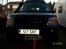
winch fitted at home in about nine hours 242 views
|
|

Tigger - Team DurtyDisco (The DoubleD's) for the Mac4x4 201354 views
|
|
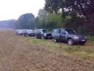
189 viewsCars belonging to the team of guns where I was picking up the other day..... A D3 was in there!!! plus 2 Supercharged RRs with MTRs and a RR Vogue
|
|
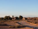
Dalhousie homestead72 views
|
|

Thread upload1 viewsImage uploaded in thread 204567
|
|

Morocco explorer4 viewsDriving on the plateau de rekkom eastern Morocco
|
|

tea beer100 views
|
|

Let it snow!146 viewsOne of our Team Leader D3's in High Wycombe, where the weather can get really bad, it's the hills you know!
|
|

29 viewsCornish inspection team
|
|
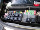
Picture of the engine compartment fuse panel5752 viewsEngine compartment fuse panel located near the battery. This is where F3E, (5 amp), F26E, (20 amp), Fuseable link 10E, (60 amp) and Relay 7E, the now upgraded 70 amp air compressor motor relay, part number YWB500220, (E is for Engine compartment fuse box), are all located. Fuse F35P, (5 amp), is inside the Passenger compartment behind the lower glove box door.
To keep the suspension from going down to the stops when driving, (or parked), it appears that it is only really necessary to remove F26E to depower the exhaust valve and generally keep all the valve block solenoid valves in a closed position trapping whatever air is within the air springs. F3E gets its power thru F26E, so when F26E is removed, the F3E circuit is automatically de-powered. F35P is more interesting in that battery power goes thru the ignition switch and F35P and then into the air suspension control unit. Apparently however, if F26E is removed, removing the F35P is not needed even when the engine is running.
With all fuses still in, if you have a problem, in practice, ideally, the compressor still works and will raise the 3 to an appropriate height. If so, one can then shut the engine off and allow the computers to go to sleep and then you remove the fuse(s). In actual practice, it seems that one need only pull the F26E fuse and can do so with the engine running. All the same, one might consider that the 3 is first a mobile computer, and secondly a 4x4. Computers prefer to go to sleep before the plug is pulled on them, however given that F26E circuit is always alive, then the computer never sleeps. With the fuse(s) pulled, and if you are still up, you can now be a 4x4 instead of a low rider. The whole purpose of the fuse pulling exercise is to depower the one and only system exhaust valve that is physically located within the compressor unit, (to keep it from opening), and secondarily to keep closed the four air spring solenoids within the block valves. This also shuts the air compressor down and stops the air compressor from making air even if the compressor is still good. That is why you initially need the fuse(s) in to allow the compressor to make air if it can.
|
|

Christmas Presents under the tree..... Don't worry we're guarding - who's on watch, Teagan or Lola?15 views
|
|
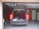
230 viewsLED\'s instead of ordinary bulbs, brake applied
|
|

Lugano104 views
|
|
Team Break52 views
|
|
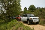
Team Break62 views
|
|
Only way across "The Plateau"59 views
|
|

209 views
|
|

139 views
|
|

120 views
|
|

127 views
|
|

147 views
|
|

120 views
|
|
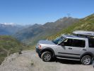
Col de la Tourmalet France 200952 viewsHolidays in France high up in the Pyrenees we decided to drive up to the top of the Pic du Midi at an altitude of 2877m instead of taking the £60-00 cable car. Just don\'t look down. What a Day!
|
|
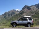
221 viewsHolidays in France high up in the Pyrenees we decided to drive up to the top of the Pic du Midi at an altitude of 2877m instead of taking the £60-00 cable car. Just don\'t look down. What a Day!
|
|
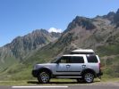
58 viewsHolidays in France high up in the Pyrenees we decided to drive up to the top of the Pic du Midi at an altitude of 2877m instead of taking the £60-00 cable car. Just don\'t look down. What a Day!
|
|
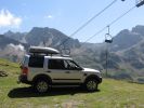
Why take the lift when you have a Landrover49 viewsHolidays in France high up in the Pyrenees we decided to drive up to the top of the Pic du Midi at an altitude of 2877m instead of taking the £60-00 cable car. Just don't look down. What a Day!
|
|
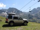
Why take the lift when you have a Landrover232 viewsHolidays in France high up in the Pyrenees we decided to drive up to the top of the Pic du Midi at an altitude of 2877m instead of taking the £60-00 cable car. Just don\'t look down. What a Day!
|
|
teaser 1398 views
|
|
teaser 2353 views
|
|

PNC team56 views
|
|
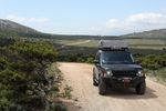
plateau38 views
|
|

Interstate Battery Dimension sheet640 viewsThis sheet is hard to find - the sheet is not on the Interstate corporate web site but some dealer web sites display it. The pdf shows most of their available batteries including the H7 and H8 sizes that are the LR North America replacement batteries for the main starting battery. These batteries are of the Land Rover desired "shallow" cycle high discharge current Maintenance Free, (Ca Ca), internal construction, (not AGM, but instead, Wet Flooded Lead Acid with battery "caps" and Ca grid separators).
For the AUX battery , the H6, (BCI Group 48), is probably similar in dimensions to the Varta E12V75N that is popular in Australia. For that battery to fit in the second battery compartment, you must grind out the angled nibs on the inside front bottom of the LR black plastic surround, something I did wish to do and hence installed a Group 40R on a spacer. Alternately, one can choose an Interstate BCI Group 47 which is similar to a DIN H5 for the AUX location. I did this when I had to replace my 40R. No vertical spacer is required and the stock battery tie down bolts and clamp work well.
|
|

I in Team13 views
|
|

Replacement switch from RRS installed on LR3861 viewsThe switch shown is LR part number YUZ500020, the upper rear hatch release switch that is found on the Range Rover Sport.
The switch body is the same switch as on the LR3 except that there is no wiring disconnect on the LR3. Hence when the switch corrodes and requires replacement, the LR solution is to purchase a new handle and license plate light assembly. I instead cut off the old switch and installed a JAE mating connector to the existing wiring and hence just plugged the RRS switch in.
The replacement RRS switch snaps into the same rectangular space in the same manner as the removed LR3 switch, the difference is the JAE male wiring connector.
|
|

Thread upload8 viewsImage uploaded in thread 179070
|
|
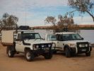
Lake Coongey. The project vechle and Micheals mighty D3142 viewsStoped for lunch and to do some boating with the inflateable boat, kids paddled to the other side and after trying to call them back D2 was dispatched to the other side to bring them bach but by thr time D2 got to the other side they had paddled back, we thought if was funney but the D2 driver definitly did not, ha ha ha!
|
|

Thermostat Housing LR005631527 viewsWhen the time comes to install a new thermostat, consider installing the whole housing instead.
Advantages are the thermostat is correctly installed, (not as simple as it should be); you get all new plastic and that is important, plus a new coolant temperature sensor and also a new heater coolant bypass valve, the secret part no one realizes is also within.
The cost of the whole assembly is not much more than the cost of a factory thermostat and the effort to replace all is not as difficult as it might seem.
|
|

Battery Maintainer pigtail sticking out of Grill723 viewsThis is all you see when everything is put back together - just the pigtail and Weather Pack blanking plug. Most often, I have it all tucked back behind the grill.
In winter, there may be a second cord hanging out as well - the 120 VAC power cord for the engine block heater, a tea kettle like element inserted in the engine block. NAS petrol V8's do not have the Fuel Burning Heater, (FBH), installed, but instead in cold area markets have the block heater element assembly available as a dealer installed option. There is an argument to say that the heating element is factory installed in all cold climate V8 gasoline engines, however the appropriate power cord is not. If true, this means that all one needs to purchase is the area specific power cord and plugging in / attachment to the engine block located block heater.
As such, you will often see a conventional 120VAC three prong power plug hanging loose out of the grill of most vehicles here in the wintertime. In summer, most drivers tuck the plug back behind the grill as it is no beauty mark.
|
|
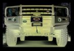
275/70R17 MTR teaser428 views
|
|
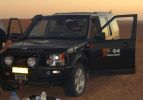
Brits and their tea!106 viewsWhenever there's a problem to solve - put the kettle on. After running out of fuel, 18km from the nearest balcktop and fuel station, 3 of the team's cars waited for the return of the other two with fuel. What does one do at times like these? Have a nice tidy up inside, dust off the sand and put the kettle on for a cuppa tea.
|
|

LR3 Denso Alternator YLE500390 pulley view817 viewsNote the DENSO sticker on the side. Denso calls their nominal 150 amp 12 Volt alternator an SC2 design. SC means Segment Conductor which apparently increase the winding density of the stator coil, hence yielding a physically smaller lighter alternator for a given output. I presume the 2 means the second try at getting it right. A Denso part number is 4280003690 for the alternator, (there are others, as below).
Rotation is clockwise and the 54mm diameter pulley has 6 grooves (PV6x54). Count the pulley grooves on both the one you remove and your new one - some replacement alternators seem to ship with 5 or 7 grooves so you might be swapping pulleys.
A previous LR part number was YLE500190 for the older variation of the newer YLE500390 unit.
An additional part number for a factory rebuilt is Nippon Denso 210-0569 for the petrol V8 alternator. Other Nippon Denso numbers include 104210-3690 and 104210-3691. The Lester number is 11206 which relates to another Denso number of 290-5287. WAI uses 11206N.
From 2006 to 2009, the internal regulator is a Transpo IN6349 and of the B circuit type if it can be said that applies to PWM, (Pulse Width Modulated), regulators.
The "regulator" inside the alternator is therefore really not a regulator in the old sense of the term but instead an instruction receiver from the ECM that translates Pulse Width Modulated (PWM) signals into a form that the alternator understands – digital like signals from the Engine Control Module(ECM) into analogue like signals that the windings understand.
|
|

Horn Wiring Circuit LR3575 viewsThe is the wiring diagram for the dual horn circuit.
The Horn Relay, (R133), is not a big black thing hidden somewhere but instead what is called a FET, (and it is hidden)!
This is a Field Effect Transistor that is built into the circuit board that is mounted to the back of the fuse box that is located behind the lower glove box door on the passenger side of the 3. The related 15 amp fuse, 12P, is mounted in this fuse box and is often called F12P, where F is for fuse, and P is for Passenger compartment.
This is to help differentiate from another fuse and relay box, (the usual kind), that is located beside the starting battery in the Engine compartment. FxxE is often used in the naming of those fuses.
|
|
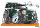
disco 3 koolart image on tea/coff mug £6.99 or on white heavy weight sublimation t shirt £10.99 personalised25 viewschange body work color for free...most colors available. t shirts in 5 sizes......
|
|

LTE Motorsport Supermoto Stable50 views
|
|

Lugano Teal431 views
|
|
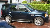
Lugano Teal387 views
|
|
My Trek 97 team96 views
|
|

Marmaris Teal619 views
|
|
Thread upload8 viewsImage uploaded in new thread
|
|
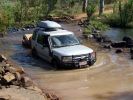
D3 in the Kimberley - on the track to the Mitchell Falls, crossing the King Edward River49 viewsSix weeks after the tharck has been opened the water levels in the King Edward River have greatly reduced. This is the start of the 80km track up onto the Mitchell Plateau.
|
|

30 views
|
|
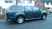
My Isuzu DMAX with Truckman Max Canopy25 viewsFinally got all the bits I paid for from the dealer - a Truckman Max Canopy and a spare wheel - unbelievably the default option on these is a can of foam and a compressor - thick end of £290 to get a full sized spare and the hoist to sling it underneath (much the same as a Disco, which means equally as stealable, might need to acquire a 17" spare protector of Uncle Ray)
|
|
22 views
|
|
57 views
|
|
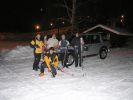
369 viewsSki Team Disco3
|
|
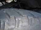
Tread tear34 views
|
|
![Filename=PANO_20150620_093847[1].jpg
Filesize=163KB
Dimensions=1280x317
Date added=24.Jun 2015 PANO_20150620_093847[1].jpg](albums/userpics/42570/thumb_PANO_20150620_093847%5B1%5D.jpg)
Chateau de Thenissey4 viewshttp://www.chateaudethenissey.com/
|
|
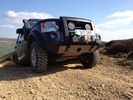
Climbing Rudland Rig 210 viewsClimbing Rudland Rig
|
|
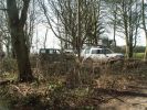
Tea stop in the woods174 views
|
|
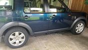
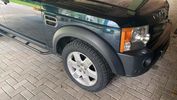
New Rubber26 viewsToday my new Pirellis are installed.
|
|
28 views
|
|
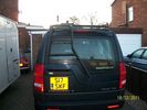
Pro speed ladder 262 views
|
|
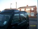
pro speed rack 249 views
|
|
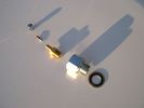
Reservoir Air In fittings exploded view 1885 viewsThis shows the fittings required for the mod. The reducer adaptor requires a 27mm socket and is M20 x 1.5 male thread x 1/4" NPT female. The 1/4" male NPT Schrader valve has the standard valve core removed and an AN/MIL spec aircraft oleo strut valve installed instead.
A standard automobile valve is rated at 200 psig, (14 bar); the air tank runs closer to 244 psig, (16.8 bar), with the relief valve set to open between 334 psig, (23 bar) and 370 psig (25.5 bar). The aircraft valve is rated at 2,000 psig, (138 bar).
|
|
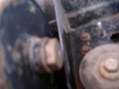
Reservoir Bung 24mm socket 1149 viewsThis is the view of the air tank at the end nearest the front left wheel. This is what you see before you do the mod. The other view is after the mod.
On pre 2008 models, there is this 24mm socket hex head bung, M20 x 1.5 thread, that can be unscrewed and the Schrader valve assembly installed instead. On newer 3's the bung hole was deleted from the front end of the air tank; hence the mod as described, is then not possible.
|
|

Rosen A10 Manufacturer Installation Manual759 viewsThis is a 30 page pdf from Rosen that explains how to install the A10 unit. It is Generic in nature and hence carries detail not found in the LR specific install instructions. It also uses words and pictures instead of just pictures, hence can be a bit easier to figure out, particularily if you wish to take advantages of some of the hidden features not described in the LR material.
One of these features is how to hook up to a headrest display or I suppose even to the NAV in front.
|
|
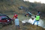
Team Santa to the rescue201 views
|
|

Oldham Mountain Rescue Team Bulletin Sept 2009105 viewsQuarterly Bulletin of the Rescue Team
|
|
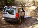
Ready steady...126 views
|
|

55 views
|
|

Thread upload5 viewsImage uploaded in thread 193352
|
|
Thread upload5 viewsImage uploaded in thread 108789
|
|

Thread upload5 viewsImage uploaded in thread 159579
|
|
98 views
|
|

Thread upload1 viewsImage uploaded in thread 200758
|
|
Thread upload42 viewsImage uploaded in thread 101136
|
|

Thread upload6 viewsImage uploaded in thread 128311
|
|
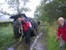
Stuck D452 viewsCrack Recovery Team Jumps into action
|
|
Bonnet Knome90 views
|
|
Adams new machine67 views
|
|

Baskets75 views
|
|

Quick Brew???4 views
|
|

Thread upload4 viewsImage uploaded in new thread
|
|

Thread upload30 viewsImage uploaded in thread 187407
|
|
165 views
|
|
172 views
|
|

443 views
|
|

8 views
|
|

Thread upload11 viewsImage uploaded in thread 148776
|
|
Thread upload7 viewsImage uploaded in thread 163880
|
|
Thread upload6 viewsImage uploaded in thread 163880
|
|
107 viewsThe tires didn't make it.
|
|

171 views
|
|
Where they went, I went..197 views
|
|

Two-part trim clip463 viewsThis is what I used to fix the Large Rear Mud flaps instead of my first attempt with screws - these actually cameof the vehicle when I fitted RLD's rock sliders
|
|
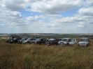
The team347 views
|
|
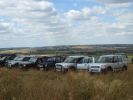
The team374 views
|
|
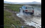
oh FOOK95 viewsthe range took in a heap of muddy water in through the air intake and swallowed it and spat it out its arse as steam. how the engine survived, i do not know. video coming soon. Definatly worth a look!
|
|

DiscoDancers Desert crossing84 viewsThe team consisted of two LR3 V8s, a Disco II V8, and two Nissan Patrol Safaris. 168 km of dune crossings over 2 days with a camp overnight mid-way. Awesome!
|
|
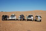
The team photo103 viewsTaken at the finish point - just 60 km from the nearest blacktop road! A Challenge indeed, especially as at this point fuel in 3 cars was close to the red line with 20 litres of reserve between all 5 cars!
|
|
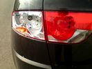
whoops77 viewsLatest score form the wife is
Skip 1 - 0 Seat Altea
|
|
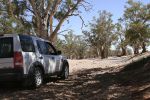
Willochra Creek849 viewsCALENDAR 2008 ENTRY
parking in the shade for some tea and lunch in Willochra Creek bed which drains into lake Torrens in South Australia. Three weeks prior, this creek was 300m wide with recent flooding rainfalls.
|
|

Thread upload3 viewsImage uploaded in thread 149931
|
|
|
|
|
|