| Search results - "voltage" |
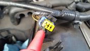
Test probe measure voltage15 viewsDo NOT insert the test probe into the connector as this can damage the terminal.
|
|

Alternator Plug and B+ terminal912 viewsPictured is the rear of the older Land Rover part # YLE500190 alternator showing the shiny cooling fin of the Regitar VRH2005-142 regulator under.
The first pin in the far left side of the connector is numbered #1 in the LR electrical wiring diagrams and is Battery Voltage Sensing (BVS); the middle pin, #2 receives a Pulse Width Modulated (PWM) signal from the Engine Control Module (ECM), and the right pin, #3 carries a PWM signal back to the ECM. Terminal Pin #2 on the LR wiring diagrams is called Alternator Control or ALT CON; Pin #3 per LR is called Alternator Monitoring or ALT MON.
Pin #1 is similar to what in older designs used to be called A or Batt, but is now called by Denso, S, AS, or Alternator Sensing for this design. Pin #1 also provides power to excite the alternator at startup until the PWM instructions over ride the battery voltage info. Land Rover calls the electronics under the pins a Smart Regulator, ironic, as it has to follow orders from the ECM rather than give the orders - new age thinking I guess. This is different from older design internal regulators that look at just the battery or the electrical buss voltage and then decides itself what to do.
It is almost like we are back to the external regulator designs of old, except that the ECM may decide that instead of telling the alternator to make more power, to load shed, and hence shut down the heated windscreen, seats, or whatever other electrical loads it decides are appropriate. My view is that the "smarts" are in the ECM and that the "regulator" should be regarded if not dumb, then as being a slave to the ECM.
|
|

amps-acid-car-battery-soc-charge-voltage-3d23 views
|
|

Thread upload13 viewsImage uploaded in new thread
|
|

Thread upload25 viewsImage uploaded in thread 103032
|
|

Thread upload13 viewsImage uploaded in thread 135852
|
|

Thread upload14 viewsImage uploaded in new thread
|
|

Battery Voltage Chart32 views
|
|

Battery Voltage SoC63 views
|
|

056231 viewsP0562 SYSTEM VOLTAGE (ENGINE SIDE) TOO LOW
|
|

Charging voltage with a/c on127 views
|
|
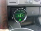
Charging voltage97 views
|
|
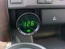
Battery voltage145 views
|
|
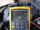
Voltage 10 seconds after start48 views
|
|
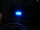
Voltage on cheap cigar lighter meter53 views
|
|
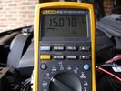
Voltage 40 seconds after start52 views
|
|
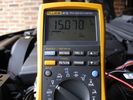
Fluke Alternator Voltage21 views
|
|
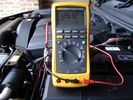
Battery Voltage54 views
|
|
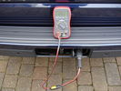
Tow electrics voltage20 views
|
|
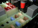
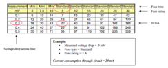
Voltage Drop on 25A32 views25 Amp Fuse = 2.36mOhm or 0.00236 Ohms
Measured @ 0.0235v or 23.5mV
= 9.95763A ~ 10A
|
|
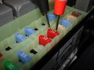
Voltage Drop on 10A29 views
|
|

EAS- inputs - voltages and heights121 views
|
|

File - Fuse_Voltage_Drop_Chart_-_Cartridge_Fuse26 views
|
|

Fuse Voltage Drop Cartridge35 views
|
|

File - Fuse_Voltage_Drop_Chart_-_Maxi_Fuse17 views
|
|

File - Fuse_Voltage_Drop_Chart_-_Mini_Fuse21 views
|
|

Fuse Voltage Drop Mini53 views
|
|

File - Fuse_Voltage_Drop_Chart_-_Standard_Fuse20 views
|
|
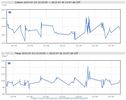
189 views
|
|
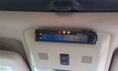
Battery check display15 viewsI mounted a digital battery display in order to see the voltage on the auxiliary battery.
There's also a thermometer which gives the inner and outer (via a side switch) values.
The display is switched on/off via another rocker switch.
|
|
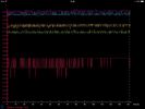
Dented Disco's Alternator Voltage24 views
|
|
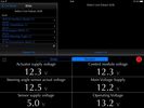
D4 system voltages16 views
|
|

Battery voltages23 views
|
|

LP scoped 219 viewsBy connecting a Low Amps probe to the fuel pump's voltage supply wire, you can view the pump's current waveform on a digital storage oscilloscope (DSO). The scope pattern will reveal internal wear in the brushes and commutator that may not show up in a traditional pressure or volume test.
Observing the waveform will show if the pump's amp draw is normal for the application or is high or low, and if the pump is operating at normal speed or is running slow. Problems such as a bad spot on a commutator or a short or open in the armature also will be obvious in the waveform.
A "good" electric fuel pump waveform will generally seesaw back and forth with relative consistency and minimal variation between the highs and lows. A "bad" waveform will show large or irregular drops in the pattern, with large differences between the highs and lows.
|
|

LED Voltage display44 views
|
|

LED Voltage display32 views
|
|

LED Voltage display29 views
|
|

LED Voltage display29 views
|
|

LED voltage display32 views
|
|

faulty radio ..shutting down before the required voltage155 views
|
|
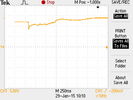
Cranking voltage new battery17 viewsMore details in .csv file
|
|

Cranking voltage new battery19 viewsDetailed measurement numbers of the new.jpg file.
|
|
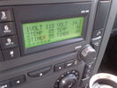
Voltage Display Page Radio Head Unit 118 14.2839 viewsThis shows the voltage/temperature/timer display page within the 6CD-465 radio head. There is a second file within this album, a doc file, that outlines the procedure to access the diagnostics.
The 14.1 volts number was the approximate vehicle system voltage with the engine running; the 118 number infers 11.8 volts which is the low power infotainment system shutdown cutoff voltage. The factory default setting is 135 or about 13.5 volts. By holding the keypad 1 button down, the 3 digit volts numbers will decrease 001 at a time until the keypad 1 button is released. Decreasing the number from 135 to some lower number should increase the time the system will remain on with the engine off.
The TEMP numbers refer to Fuel Burning Heater, (FBH), temperature values. 85 is apparently a high limit and 46 was the number when the jpg was taken. This number varies and given that there is no diesel fueled FBH in our NAS petrol engine vehicles, what the value refers to is unclear. The TIMER numbers also relate to the diesel fuel burning engine heater and perhaps make more sense being 00.
|
|

Air Compressor 70 amp replacement relay1384 viewsThere is a software update, 09 April 2010, LTB00270, for the compressor which reduces the shut down pressure to about 205 psig (14 bar). The update is usually done when changing to a new compressor and also includes replacing the R7 relay in the engine compartment fuse box, 07 DEC 2010 LTB00331.
The newer grey case coloured relay, part # YWB500220, shows to be rated at 70 amps, (the relay, not the compressor), however the previous black case coloured relay also indicates 70 amps.
Both the new and replaced relay show on their wiring diagrams to have a parallel voltage spike resistor, (probably 560 ohms), across the coil terminals, #1 and #2. This means one does not just replace the relay with any four prong 70 amp ISO sized relay that one happens upon.
One presumes the grey relay is either upgraded or just being installed for good measure. The relay is common on Ford Fiesta for the seat heater relay, Ford part number 5M5T 14B 192 EA; also Volvo, part number 30765034. The Tyco part number moulded on the grey body is V23136-J4-X62.
|
|

Voltage reading72 viewsHere is the voltage to the heated seat. Engine running. Did not enable heat on the hvac.Why 14v there now?
|
|
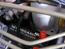
12v Isolator875 viewsEnsures that aux ery won\'t charge until the main batt is topped up and won\'t drain the main batt. I used the biggest I could find to take the load with no stress - especially the higher voltage on the landy. Came as a compete kit and works well.
|
|

ScanGauge II on steering column of LR3800 viewsMAP is Manifold Absolute Pressure, what I call Vacuum.
The volts is I think the battery charging voltage as it moves around from about 12.4 when shut down to 13.5 when the batteries seems charged; 14.9 is about as high as I have seen it display.
You also have RPM, speed in MPH or KPH, coolant temperature and a bunch of other readings including sort of instantaneous fuel in a variety of units.
Also under some conditions, the ScanGauge will reset the MIL light as well. The background colour of the display can be changed to many different colours. I have it set to match the LR green.
|
|

Thread upload3 viewsImage uploaded in thread 191860
|
|

Tick over9 viewsVoltage at tick over.
|
|

Thread upload24 viewsImage uploaded in thread 105683
|
|

File - Voltage_Drop_121 views
|
|

Thread upload20 viewsImage uploaded in thread 105683
|
|

File - Voltage_Drop_216 views
|
|
File - Voltage_Drop_321 views
|
|
Thread upload21 viewsImage uploaded in thread 105683
|
|
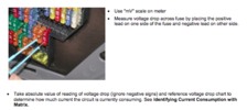
File - Voltage_Drop_418 views
|
|
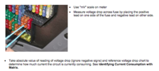
Thread upload14 viewsImage uploaded in thread 107180
|
|
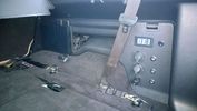
PS2 + Split charge system 10 viewsPS2 - Wireless controllers and headphones.
Split charge system with auxiliary sockets with digital voltage display
|
|
|
|
|
|